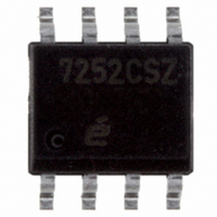
EL7252CSZ Intersil, EL7252CSZ Datasheet

EL7252CSZ
Specifications of EL7252CSZ
Available stocks
Related parts for EL7252CSZ
EL7252CSZ Summary of contents
Page 1
... CAUTION: These devices are sensitive to electrostatic discharge; follow proper IC Handling Procedures. 1-888-INTERSIL or 1-888-468-3774 Copyright Intersil Americas Inc. 2003, 2005, 2008, 2009. All Rights Reserved All other trademarks mentioned are the property of their respective owners. EL7242, EL7252 July 29, 2009 FN7285.4 | Intersil (and design registered trademark of Intersil Americas Inc. ...
Page 2
... EL7242CN (Note 2) EL7242CS (Note 2) EL7242CS-T7* (Note 2) EL7242CS-T13* (Note 2) EL7252CSZ (Note 1) EL7252CSZ-T7* (Note 1) EL7252CSZ-T13* (Note 1) EL7252CN EL7252CS EL7252CS-T7* (Note 2) EL7252CS-T13* (Note 2) *Please refer to TB347 for details on reel specifications. **Pb-free PDIPs can be used for through hole wave solder processing only. They are not intended for use in Reflow solder processing applications. ...
Page 3
... EL7242, EL7252 Thermal Information = +25°C) Power Dissipation 8 Ld SOIC . . . . . . . . . . . . . . . . . . . . . . . . . . . . . . . . . . . . .570mW 8 Ld PDIP .1050mW Pb-Free Reflow Profile .see link below http://www.intersil.com/pbfree/Pb-FreeReflow.asp *Pb-free PDIPs can be used for through hole wave solder processing only. They are not intended for use in Reflow solder processing applications ...
Page 4
Timing Table Standard Test Configuration Simplified Schematic V+ INPUT INPUT BUFFER 4 EL7242, EL7252 5V INPUT 2.5V 0 90% INVERTED OUTPUT 10% 90% NON-INVERTED OUTPUT 10 EL7242 1 OUTPUT 7 2 ...
Page 5
Typical Performance Curves 1.0 PDIP8 1.05W θ = 95°C/W JA 0.8 MAX T 570mW J 0.6 0.4 SO8 0.2 θ = 175°C AMBIENT TEMPERATURE (°C) FIGURE 1. MAX POWER/DERATING CURVES 10 2/DIV 0 -10 ...
Page 6
Typical Performance Curves 100 V = +15V +10V 0.1 10k 100k FREQUENCY (Hz) FIGURE 7. AVERAGE SUPPLY CURRENT vs VOLTAGE AND FREQUENCY 100 100 10V = 10V ...
Page 7
Typical Performance Curves 7 EL7242, EL7252 (Continued 10V 1000pF L 0 -50 - TEMPERATURE (°C) FIGURE 13. DELAY vs TEMPERATURE 100 125 FN7285.4 ...
Page 8
Small Outline Package Family (SO PIN #1 I.D. MARK 0.010 SEATING PLANE 0.004 C 0.010 MDP0027 SMALL OUTLINE PACKAGE FAMILY (SO) SYMBOL SO-8 SO-14 ...
Page 9
... Accordingly, the reader is cautioned to verify that data sheets are current before placing orders. Information furnished by Intersil is believed to be accurate and reliable. However, no responsibility is assumed by Intersil or its subsidiaries for its use; nor for any infringements of patents or other rights of third parties which may result from its use ...


