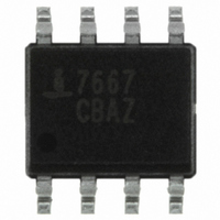
ICL7667CBAZA-T Intersil, ICL7667CBAZA-T Datasheet - Page 8

ICL7667CBAZA-T
Manufacturer Part Number
ICL7667CBAZA-T
Description
IC MOSFET DRIVER DUAL 8-SOIC
Manufacturer
Intersil
Datasheet
1.ICL7667CPAZ.pdf
(10 pages)
Specifications of ICL7667CBAZA-T
Configuration
Low-Side
Input Type
Inverting
Delay Time
20ns
Current - Peak
1A
Number Of Configurations
2
Number Of Outputs
2
Voltage - Supply
4.5 V ~ 15 V
Operating Temperature
0°C ~ 70°C
Mounting Type
Surface Mount
Package / Case
8-SOIC (3.9mm Width)
Rohs Compliant
Yes
Lead Free Status / RoHS Status
Lead free / RoHS Compliant
High Side Voltage - Max (bootstrap)
-
Other names
ICL7667CBAZA-TTR
Available stocks
Company
Part Number
Manufacturer
Quantity
Price
Company:
Part Number:
ICL7667CBAZA-T
Manufacturer:
MICROCHIP
Quantity:
1 001
Other Applications
Relay and Lamp Drivers
The ICL7667 is suitable for converting low power TTL or
CMOS signals into high current, high voltage outputs for
relays, lamps and other loads. Unlike many other level
translator/driver ICs, the ICL7667 will both source and sink
current. The continuous output current is limited to 200mA
by the I
Charge Pump or Voltage Inverters and Doublers
The low output impedance and wide V+ range of the
ICL7667 make it well suited for charge pump circuits. Figure
13A shows a typical charge pump voltage inverter circuit and
a typical performance curve. A common use of this circuit is
to provide a low current negative supply for analog circuitry
or RS232 drivers. With an input voltage of +15V, this circuit
will deliver 20mA at -12.6V. By increasing the size of the
capacitors, the current capability can be increased and the
voltage loss decreased. The practical range of the input
frequency is 500Hz to 250kHz. As the frequency goes up,
the charge pump capacitors can be made smaller, but the
internal losses in the ICL7667 will rise, reducing the circuit
efficiency.
Figure 14, a voltage doubler, is very similar in both circuitry
and performance. A potential use of Figure 13 would be to
supply the higher voltage needed for EEPROM or EPROM
programming.
1kHz - 250kHz
SQUARE
LEVELS
IN TTL
WAVE
2
R power dissipation in the output FETs.
1/2
ICL7667
+15V
FIGURE 13A.
10
+
µ
8
F
-
IN4001
IN4001
+
-
FIGURE 13. VOLTAGE INVERTER
47
µ
F
-13.5V
ICL7667
Clock Driver
Some microprocessors (such as the CDP68HC05 families)
use a clock signal to control the various LSI peripherals of
the family. The ICL7667s combination of low propagation
delay, high current drive capability and wide voltage swing
make it attractive for this application. Although the ICL7667
is primarily intended for driving power MOSFET gates at
15V, the ICL7667 also works well as a 5V high-speed buffer.
Unlike standard 4000 series CMOS, the ICL7667 uses short
channel length FETs and the ICL7667 is only slightly slower
at 5V than at 15V.
1kHz - 250kHz
FIGURE 13B. OUTPUT CURRENT vs OUTPUT VOLTAGE
-10
-12
-14
-4
-6
-8
SQUARE
LEVELS
5
IN TTL
WAVE
FIGURE 14. VOLTAGE DOUBLER
20
1/2
ICL7667
+15V
SLOPE = 60Ω
40
+
10
I
OUT
µ
-
F
(mA)
+15
60
IN4001
f = 10kHz
IN4001
80
+
-
47
April 29, 2010
µ
F
FN2853.6
100
28.5V


