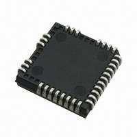
IRS26302DJPBF International Rectifier, IRS26302DJPBF Datasheet - Page 27

IRS26302DJPBF
Manufacturer Part Number
IRS26302DJPBF
Description
IC BRIDGE +1 GATE DVR 3PH 44PLCC
Manufacturer
International Rectifier
Datasheet
1.IRS26302DJTRPBF.pdf
(51 pages)
Specifications of IRS26302DJPBF
Configuration
3 Phase Bridge
Input Type
Non-Inverting
Delay Time
320ns
Current - Peak
200mA
Number Of Configurations
1
Number Of Outputs
3
High Side Voltage - Max (bootstrap)
600V
Voltage - Supply
10 V ~ 20 V
Operating Temperature
-40°C ~ 125°C
Mounting Type
Surface Mount
Package / Case
44-PLCC (32 Leads)
Number Of Drivers
6
Driver Configuration
Non-Inverting
Driver Type
High and Low Side
Input Logic Level
CMOS/TTL
Rise Time
190ns
Fall Time
75ns
Propagation Delay Time
710ns
Peak Output Current
350mA
Power Dissipation
4.6W
Operating Supply Voltage (min)
10V
Turn Off Delay Time
50ns
Turn On Delay Time (max)
50ns
Operating Temp Range
-40C to 125C
Operating Temperature Classification
Automotive
Mounting
Surface Mount
Pin Count
32
Package Type
PLCC
Lead Free Status / RoHS Status
Lead free / RoHS Compliant
Available stocks
Company
Part Number
Manufacturer
Quantity
Price
Company:
Part Number:
IRS26302DJPBF
Manufacturer:
International Rectifier
Quantity:
10 000
IRS26302DJ
Advanced Input Filter
The advanced input filter allows an improvement in the input/output pulse symmetry of the HVIC and helps to reject
noise spikes and short pulses. This input filter has been applied to the HIN, LIN, PFCin and EN inputs. The working
principle of the new filter is shown in Figures 19 and 20.
Figure 19 shows a typical input filter and the asymmetry of the input and output. The upper pair of waveforms
(Example 1) show an input signal with a duration much longer then t
; the resulting output is approximately the
FIL,IN
difference between the input signal and t
. The lower pair of waveforms (Example 2) show an input signal with a
FIL,IN
duration slightly longer then t
; the resulting output is approximately the difference between the input signal and
FIL,IN
t
.
FIL,IN
Figure 20 shows the advanced input filter and the symmetry between the input and output. The upper pair of
waveforms (Example 1) show an input signal with a duration much longer then t
; the resulting output is
FIL,IN
approximately the same duration as the input signal. The lower pair of waveforms (Example 2) show an input signal
with a duration slightly longer then t
; the resulting output is approximately the same duration as the input signal.
FIL,IN
Figure 19: Typical input filter
Figure 20: Advanced input filter
Short-Pulse / Noise Rejection
This device’s input filter provides protection against short-pulses (e.g., noise) on the input lines. If the duration of the
input signal is less than t
, the output will not change states. Example 1 of Figure 21 shows the input and output in
FIL,IN
the low state with positive noise spikes of durations less than t
; the output does not change states. Example 2 of
FIL,IN
Figure 21 shows the input and output in the high state with negative noise spikes of durations less than t
; the
FIL,IN
output does not change states.
Figure 21: Noise rejecting input filters
www.irf.com
© 2009 International Rectifier
27


