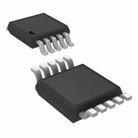
LM5106MMX/NOPB National Semiconductor, LM5106MMX/NOPB Datasheet - Page 2

LM5106MMX/NOPB
Manufacturer Part Number
LM5106MMX/NOPB
Description
IC DVR HALF-BRIDGE HV 10-MSOP
Manufacturer
National Semiconductor
Datasheet
1.LM5106MMNOPB.pdf
(12 pages)
Specifications of LM5106MMX/NOPB
Configuration
Half Bridge
Input Type
PWM
Delay Time
115ns
Current - Peak
1.8A
Number Of Configurations
1
Number Of Outputs
2
High Side Voltage - Max (bootstrap)
118V
Voltage - Supply
8 V ~ 14 V
Operating Temperature
-40°C ~ 125°C
Mounting Type
Surface Mount
Package / Case
10-MSOP, Micro10™, 10-uMAX, 10-uSOP
Lead Free Status / RoHS Status
Lead free / RoHS Compliant
Other names
LM5106MMX
Available stocks
Company
Part Number
Manufacturer
Quantity
Price
Part Number:
LM5106MMX/NOPB
Manufacturer:
TI/德州仪器
Quantity:
20 000
www.national.com
LM5106MM
LM5106MMX
LM5106SD
LM5106SDX
Connection Diagram
Ordering Information
Pin Descriptions
Pin
NA
10
Ordering Number
1
2
3
4
5
6
7
8
9
Name
VDD
RDT
VSS
HO
HB
HS
NC
EN
LO
EP
IN
Positive gate drive supply
High side gate driver bootstrap
rail
High side gate driver output
High side MOSFET source
connection
Not Connected
Dead-time programming pin
Logic input for driver Disable/
Enable
Logic input for gate driver
Ground return
Low side gate driver output
Exposed Pad
Description
Package Type
MSOP-10
MSOP-10
LLP-10
LLP-10
See NS Number MUB10A, SDC10A
10-Lead MSOP or LLP
Decouple VDD to VSS using a low ESR/ESL capacitor, placed as close to the
IC as possible.
Connect the positive terminal of bootstrap capacitor to the HB pin and connect
negative terminal to HS. The Bootstrap capacitor should be placed as close to
IC as possible.
Connect to the gate of high side N-MOS device through a short, low inductance
path.
Connect to the negative terminal of the bootststrap capacitor and to the source
of the high side N-MOS device.
A resistor from RDT to VSS programs the turn-on delay of both the high and
low side MOSFETs. The resistor should be placed close to the IC to minimize
noise coupling from adjacent PC board traces.
TTL compatible threshold with hysteresis. LO and HO are held in the low state
when EN is low.
TTL compatible threshold with hysteresis. The high side MOSFET is turned on
and the low side MOSFET turned off when IN is high.
All signals are referenced to this ground.
Connect to the gate of the low side N-MOS device with a short, low inductance
path.
The exposed pad has no electrical contact. Connect to system ground plane
for reduced thermal resistance.
NSC Package Drawing
2
MUB10A
MUB10A
SDC10A
SDC10A
20175901
Application Information
1000 shipped as Tape & Reel
3500 shipped as Tape & Reel
1000 shipped as Tape & Reel
4500 shipped as Tape & Reel
Supplied As


