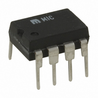
MIC5013BN Micrel Inc, MIC5013BN Datasheet

MIC5013BN
Specifications of MIC5013BN
Available stocks
Related parts for MIC5013BN
MIC5013BN Summary of contents
Page 1
... Implements high- or low-side switches Applications • Lamp drivers • Relay and solenoid drivers • Heater switching • Power bus switching • Motion control Ordering Information Part Number Standard MIC5013BN MIC5013YN –40ºC to +85ºC MIC5013BM MIC5013YM –40ºC to +85º =24V + 10µF 8 Fault 7 ...
Page 2
MIC5013 Absolute Maximum Ratings Input Voltage, Pin 1 Threshold Voltage, Pin 2 Sense Voltage, Pin 3 Source Voltage, Pin 4 Current into Pin 4 Gate Voltage, Pin 6 + Supply Voltage (V ), Pin 7 Fault Output Current, Pin 8 ...
Page 3
MIC5013 Electrical Characteristics + Test circuit –55°C to +125° Parameter Conditions + Supply Current 32V 7 + Logic Input Voltage 4.75V =15V Logic Input Current ...
Page 4
MIC5013 Test Circuit Typical Characteristics Supply Current SUPPLY VOLTAGE (V) High-side Turn-on Time* 350 300 250 200 150 100 ...
Page 5
MIC5013 Typical Characteristics (Continued) Low-side Turn-on Time for Gate = 5V 1000 300 C GATE 100 GATE SUPPLY VOLTAGE (V) Turn-off Time GATE ...
Page 6
MIC5013 Block Diagram 1 Input LOGIC Fault 8 Applications Information Functional Description (refer to block diagram) The various MIC5013 functions are controlled via a logic block connected to the input pin 1. When the input is low, all functions are ...
Page 7
MIC5013 Applications Information Control Input R 10kΩ Circuit Topologies The MIC5013 is suited for use in high- or low-side driver applications with over-current protection for both current- sensing and standard MOSFETs. In addition, the MIC5013 works well in applications where, ...
Page 8
MIC5013 Applications Information Control Input R 20kΩ inductive switching transients. The MIC5013 supply should be limited to 15V in low-side topologies; otherwise, a large current will be forced through the gate clamp zener. Low-side drivers constructed with the MIC501X family ...
Page 9
MIC5013 Applications Information MIC5013 1 Control Input Input Fault 2 Thresh V+ R TH2 R 3 1kΩ TH1 Sense Gate 22kΩ Source Gnd TH 22µF Figure 5. Time-Variable Trip Threshold (using TAB and SOURCE for forcing, and SENSE ...
Page 10
MIC5013 Applications Information 15V 33pF 100kΩ 4N35 10mA Control Input 100kΩ 1kΩ Figure 8. Improved Opto-Isolator Performance ON CR2943-NA102A ( MIC5013 (Continued) 100kΩ 100kΩ 100kΩ 100nF 10kΩ 20kΩ MPSA05 1N4148 33kΩ To MIC5013 Input Electronic ...
Page 11
MIC5013 Applications Information Since the supply current in the “OFF” state is only a small leakage, the 100nF bypass capacitor tends to remain charged for several seconds after the MIC5013 is turned off PWM application the chip supply ...
Page 12
MIC5013 Applications Information The top-side driver is based on the bootstrapped circuit of Figure 6, and cannot be switched on indefinitely. The boot- strap capacitor (1µF) relies on being pulled to ground by the bottom-side output to recharge. This limits ...
Page 13
MIC5013 Applications Information 100kΩ + 100µF 10kΩ 100Ω 330kΩ July 2005 (Continued) 12V + 10µF MIC5013 1N4148 8 1 Input Fault 2 7 Thresh V+ 20kΩ Sense Gate 4 5 Source Gnd ...
Page 14
MIC5013 Applications Information Gate Control Circuit When applying the MIC5010 helpful to understand the operation of the gate control circuitry (see Figure 14). The gate circuitry can be divided into two sections: 1) charge pump (oscillator, Q1-Q5, and ...
Page 15
... MICREL INC. 2180 FORTUNE DRIVE SAN JOSE, CA 95131 USA + 1 (408) 944-0800 TEL This information furnished by Micrel in this data sheet is believed to be accurate and reliable. However no responsibility is assumed by Micrel for its use. Micrel reserves the right to change circuitry and specifications at any time without notification to the customer. ...


