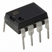
E-L6569 STMicroelectronics, E-L6569 Datasheet - Page 4

E-L6569
Manufacturer Part Number
E-L6569
Description
IC DRVR HALF BRDG HV W/OSC 8DIP
Manufacturer
STMicroelectronics
Type
Dual Peripheral Driverr
Datasheet
1.L6569A.pdf
(13 pages)
Specifications of E-L6569
Configuration
Half Bridge
Input Type
Self Oscillating
Current - Peak
175mA
Number Of Configurations
1
Number Of Outputs
2
High Side Voltage - Max (bootstrap)
600V
Voltage - Supply
10 V ~ 16.6 V
Operating Temperature
-40°C ~ 125°C
Mounting Type
Through Hole
Package / Case
8-DIP (0.300", 7.62mm)
Supply Voltage (min)
10 V
Supply Current
11 mA
Maximum Operating Temperature
+ 125 C
Mounting Style
Through Hole
Bridge Type
Half Bridge
Minimum Operating Temperature
0 C
Number Of Drivers
2
Lead Free Status / RoHS Status
Lead free / RoHS Compliant
Delay Time
-
Lead Free Status / Rohs Status
Lead free / RoHS Compliant
Other names
497-4585-5
Available stocks
Company
Part Number
Manufacturer
Quantity
Price
L6569 L6569A
ELECTRICAL CHARACTERISTCS (continued)
OSCILLATOR FREQUENCY
The frequency of the internal oscillator can be programmed using external resistor and capacitor.
The nominal oscillator frequency can be calculated using the following equation:
Where R
The device can be driven in "shut down" condition keeping the C
taken:
1. When C
2. The forced discharge of the oscillator capacitor C
Figure 1.
4/13
Symbol
V
V
RF OFF
V
limit the current discharge with a resistive path imposing R · C
V
R
RFO
V
I
DC
f
AVE
CFU
CFL
out
t
ON
BC
d
N
F
and C
F
Pin
2
3
1
6
is to GND the high side driver is off and the low side is on
RF High Level Output Voltage
RF Low Level Output Voltage
CF Upper Threshold
CF Lower Threshold
Internal Dead Time
Duty Cycle, Ratio Between Dead
Time + Conduction Time of High
Side and Low Side Drivers
On resistance of Boostrap
LDMOS
Boostrap Voltage before UVLO
Average Current from Vs
Oscillation Frequency
F
are the external resistor and capacitor.
fault signal
Parameter
f
O SC
=
---------------------------------------- -
2 R
F
R
1
C
C
I
I
V
No Load, fs = 60KHz
R
F
RF
RF
F
S
T
F
= 12K; C
= 8.2
must not be shorter than 1us: a simple way to do this is to
= 1mA
= -1mA
In2
GNDM
R
Test Condition
F
=
T
----------------------------------------- -
1.3863 R
= 1nF
F
1
2
3
4
F
pin close to GND, but some cares have to be
>1 s (see fig.1)
1
F
C
F
V
Min.
S
3.80
0.85
0.45
8
7
6
5
7.7
2.5
50
57
-0.05
Typ.
1.25
120
0.5
3.6
1.2
60
8
4
V
Max.
1.65
0.55
S
200
8.2
4.3
1.5
63
-0.2
Unit
kHz
mV
mA
V
V
V
V
s


