LMD18245T/NOPB National Semiconductor, LMD18245T/NOPB Datasheet - Page 13
LMD18245T/NOPB
Manufacturer Part Number
LMD18245T/NOPB
Description
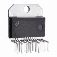
IC H BRIDGE 3A 55V TO-220
Manufacturer
National Semiconductor
Datasheet
1.LMD18245TNOPB.pdf
(21 pages)
Specifications of LMD18245T/NOPB
Applications
DC Motor Driver, Stepper Motor Driver, H Bridge
Number Of Outputs
1
Current - Output
3A
Voltage - Supply
12 V ~ 55 V
Operating Temperature
-40°C ~ 125°C
Mounting Type
Through Hole
Package / Case
TO-220-15 (Bent and Staggered Leads)
Operating Temperature Classification
Automotive
Package Type
TO-220
Operating Supply Voltage (min)
12V
Operating Supply Voltage (max)
55V
Lead Free Status / RoHS Status
Lead free / RoHS Compliant
Voltage - Load
-
Lead Free Status / Rohs Status
Compliant
Other names
*LMD18245T
*LMD18245T/NOPB
LMD18245T
*LMD18245T/NOPB
LMD18245T
Available stocks
Company
Part Number
Manufacturer
Quantity
Price
Company:

Part Number:
LMD18245T/NOPB
Manufacturer:
ST
Quantity:
14 300
Part Number:
LMD18245T/NOPB
Manufacturer:
NS/国半
Quantity:
20 000


The Typical Application
Figure 7 shows the typical application, the power stage of a
chopper drive for bipolar stepper motors. The 20 k
and 2.2 nF capacitor connected between RC and ground set
the off-time at about 48 µs, and the 20 k resistor connected
between CS OUT and ground sets the gain at about 200 mA
ONE-PHASE-ON FULL STEP DRIVE (WAVE DRIVE)
To make the motor take full steps, windings A and B can be
energized in the sequence
where A represents winding A energized with current in one
direction and A* represents winding A energized with current
in the opposite direction. The motor takes one full step each
time one winding is de-energized and the other is energized.
To make the motor step in the opposite direction, the order of
A B A* B* A
FIGURE 7. Typical Application Circuit for Driving Bipolar Stepper Motors
…,
resistor
13
per volt of the threshold for chopping. Digital signals control
the thresholds for chopping, the directions of the winding
currents, and, by extension, the drive type (full step, half
step, etc.). A µprocessor or µcontroller usually provides the
digital control signals.
the above sequence must be reversed. Figure 8 shows the
winding currents and digital control signals for a wave drive
application of the typical application circuit.
TWO-PHASE-ON FULL STEP DRIVE
To make the motor take full steps, windings A and B can also
be energized in the sequence
and because both windings are energized at all times, this
sequence produces more torque than that produced with
AB A*B A*B* AB* AB
…,
www.national.com
01187816
Related parts for LMD18245T/NOPB
Image
Part Number
Description
Manufacturer
Datasheet
Request
R

Part Number:
Description:
IC MOTOR DRIVER FULL BRIDGE 3A TO-220-15
Manufacturer:
National Semiconductor
Datasheet:

Part Number:
Description:
H-BRIDGE MOTOR DRIVER W/ PWM
Manufacturer:
National Semiconductor
Part Number:
Description:
Manufacturer:
National Semiconductor
Datasheet:

Part Number:
Description:
3a, 55v Dmos Full-bridge Motor Driver
Manufacturer:
National Semiconductor Corporation
Datasheet:
Part Number:
Description:
National Semiconductor [8-Bit D/A Converter]
Manufacturer:
National Semiconductor
Datasheet:
Part Number:
Description:
National Semiconductor [Media Coprocessor]
Manufacturer:
National Semiconductor
Datasheet:
Part Number:
Description:
Digitally Controlled Tone and Volume Circuit with Stereo Audio Power Amplifier, Microphone Preamp Stage and National 3D Sound
Manufacturer:
National Semiconductor
Datasheet:
Part Number:
Description:
Digitally Controlled Tone and Volume Circuit with Stereo Audio Power Amplifier, Microphone Preamp Stage and National 3D Sound
Manufacturer:
National Semiconductor
Datasheet:
Part Number:
Description:
AC97 Rev 2 Codec with Sample Rate Conversion and National 3D Sound
Manufacturer:
National Semiconductor
Part Number:
Description:
Manufacturer:
National Semiconductor
Datasheet:
Part Number:
Description:
Manufacturer:
National Semiconductor
Datasheet:
Part Number:
Description:
General Purpose, Low Voltage, Low Power, Rail-to-Rail Output Operational Amplifiers
Manufacturer:
National Semiconductor
Datasheet:
Part Number:
Description:
8-bit 20 MSPS flash A/D converter.
Manufacturer:
National Semiconductor
Datasheet:
Part Number:
Description:
Low Noise Quad Operational Amplifier
Manufacturer:
National Semiconductor
Datasheet: