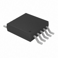
TC655EUNTR Microchip Technology, TC655EUNTR Datasheet - Page 15

TC655EUNTR
Manufacturer Part Number
TC655EUNTR
Description
IC PWM FAN SPEED CONTRLR 10-MSOP
Manufacturer
Microchip Technology
Type
High Speed PWM Controllerr
Datasheet
1.TC654EUN.pdf
(36 pages)
Specifications of TC655EUNTR
Applications
Fan Controller, Brushless (BLDC)
Number Of Outputs
1
Voltage - Supply
3 V ~ 5.5 V
Operating Temperature
-40°C ~ 85°C
Mounting Type
Surface Mount
Package / Case
10-MSOP, Micro10™, 10-uMAX, 10-uSOP
Output Current
5 mA
Operating Supply Voltage
3 V to 5.5 V
Maximum Operating Temperature
+ 85 C
Minimum Operating Temperature
- 40 C
Mounting Style
SMD/SMT
Lead Free Status / RoHS Status
Lead free / RoHS Compliant
Current - Output
-
Voltage - Load
-
Lead Free Status / Rohs Status
Lead free / RoHS Compliant
Available stocks
Company
Part Number
Manufacturer
Quantity
Price
Company:
Part Number:
TC655EUNTR
Manufacturer:
MICROCHIP
Quantity:
12 000
Part Number:
TC655EUNTR
Manufacturer:
MICROCHIP/微芯
Quantity:
20 000
5.0
5.1
The Serial Clock Input (SCLK) and the bi-directional
data port (SDA) form a 2-wire bi-directional serial port
for communicating with the TC654/TC655. The follow-
ing bus protocols have been defined:
• Data transfer may be initiated only when the bus
• During data transfer, the data line must remain
Accordingly, the following Serial Bus conventions have
been defined.
TABLE 5-1:
Transmitter
Receiver
Master
Slave
Start
Stop
ACK
Busy
NOT Busy
Data Valid
2002 Microchip Technology Inc.
is not busy.
stable whenever the clock line is HIGH. Changes
in the data line while the clock line is HIGH will be
interpreted as a START or STOP condition.
Term
SMBus 2-Wire Interface
SERIAL COMMUNICATION
The device sending data to the bus.
The device receiving data from the
bus.
The device which controls the bus: ini-
tiating transfers (START), generating
the clock and terminating transfers
(STOP).
The device addressed by the master.
A unique condition signaling the
beginning of a transfer indicated by
SDA falling (High to Low) while SCLK
is high.
A unique condition signaling the end
of a transfer indicated by SDA rising
(Low to High) while SCLK is high.
A Receiver acknowledges the receipt
of each byte with this unique condi-
tion. The Receiver pulls SDA low dur-
ing SCLK high of the ACK clock-pulse.
The Master provides the clock pulse
for the ACK cycle.
Communication is not possible
because the bus is in use.
When the bus is idle, both SDA and
SCLK will remain high.
The state of SDA must remain stable
during the high period of SCLK in
order for a data bit to be considered
valid. SDA only changes state while
SCLK is low during normal data trans-
fers. (See START and STOP condi-
tions)
TC654/TC655 SERIAL BUS
CONVENTIONS
Description
5.1.1
The TC654/TC655 support a bi-directional 2-Wire bus
and data transmission protocol. The serial protocol
sequencing is illustrated in Figure 1-1. Data transfers
are initiated by a start condition (START), followed by a
device address byte and one or more data bytes. The
device address byte includes a Read/Write selection
bit. Each access must be terminated by a Stop Condi-
tion (STOP). A convention call Acknowledge (ACK)
confirms the receipt of each byte. Note that SDA can
only change during periods when SCLK is LOW (SDA
changes while SCLK is HIGH are reserved for Start
and Stop conditions). All bytes are transferred MSB
(most significant bit) first.
5.1.2
The device that sends data onto the bus is the transmit-
ter and the device receiving data is the receiver. The
bus is controlled by a master device which generates
the serial clock (SCLK), controls the bus access and
generates the START and STOP conditions. The
TC654/TC655 always work as a slave device. Both
master and slave devices can operate as either trans-
mitter or receiver, but the master device determines
which mode is activated.
5.1.3
A HIGH to LOW transition of the SDA line while the
clock (SCLK) is HIGH determines a START condition.
All commands must be preceded by a START
condition.
5.1.4
Immediately following the Start Condition, the host
must transmit the address byte to the TC654/TC655.
The 7-bit SMBus address for the TC654/TC655 is
0011 011. The 7-bit address transmitted in the serial
bit stream must match for the TC654/TC655 to respond
with an Acknowledge (indicating the TC654/TC655 is
on the bus and ready to accept data). The eighth bit in
the Address Byte is a Read-Write Bit. This bit is a ‘1’ for
a read operation or ‘0’ for a write operation. During the
first phase of any transfer, this bit will be set = 0 to indi-
cate that the command byte is being written.
5.1.5
A LOW to HIGH transition of the SDA line while the
clock (SCLK) is HIGH determines a STOP condition.
All operations must be ended with a STOP condition.
5.1.6
The state of the data line represents valid data when,
after a START condition, the data line is stable for the
duration of the HIGH period of the clock signal.
DATA TRANSFER
MASTER/SLAVE
START CONDITION (START)
ADDRESS BYTE
STOP CONDITION (STOP)
DATA VALID
TC654/TC655
DS21734A-page 15


