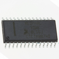
MC3PHACVDWE Freescale Semiconductor, MC3PHACVDWE Datasheet - Page 19

MC3PHACVDWE
Manufacturer Part Number
MC3PHACVDWE
Description
IC MOTOR CONTROLLER 28-SOIC
Manufacturer
Freescale Semiconductor
Datasheet
1.MC3PHACVFAE.pdf
(36 pages)
Specifications of MC3PHACVDWE
Applications
AC Motor Controller, 3 Phase
Number Of Outputs
1
Voltage - Supply
4.5 V ~ 5.5 V
Operating Temperature
-40°C ~ 105°C
Mounting Type
Surface Mount
Package / Case
28-SOIC (7.5mm Width)
Processor Series
MC3PHAC
Core
HC08
Data Bus Width
8 bit
Program Memory Type
Flash
Program Memory Size
8 KB
Data Ram Size
256 KB
Interface Type
SCI
Maximum Clock Frequency
8.2 MHz
Number Of Programmable I/os
14
Number Of Timers
2
Maximum Operating Temperature
+ 85 C
Mounting Style
SMD/SMT
Minimum Operating Temperature
- 40 C
On-chip Adc
10 bit, 4 Channel
Lead Free Status / RoHS Status
Lead free / RoHS Compliant
Current - Output
-
Voltage - Load
-
Lead Free Status / Rohs Status
Details
Available stocks
Company
Part Number
Manufacturer
Quantity
Price
Company:
Part Number:
MC3PHACVDWE
Manufacturer:
NSC
Quantity:
1 430
Standalone Application Example
Figure 12
values and jumpers have been selected to provide the following performance:
PC Master Software Operation
Introduction to PC Master Host Software
The MC3PHAC is compatible with Freescale’s PC master host software serial interface protocol.
Communication occurs over an on-chip UART, on the MC3PHAC at 9600 baud to an external master
device, which may be a microcontroller that also has an integrated UART or a personal computer via a
COM port. With PC master software, an external controller can monitor and control all aspects of the
MC3PHAC operation.
When the MC3PHAC is placed in PC master software mode, all control of the system is provided through
the integrated UART, resident on the MC3PHAC. Inputs such as START, FWD, SPEED, ACCEL,
MUX_IN, and PWMPOL_BASEFREQ have no controlling influence over operation of the system. Even
though the SPEED, START, and FWD inputs are disabled while the system is in PC master software
mode, through PC master software, it is possible to monitor the state of those inputs.
The most popular master implementation is a PC, where a graphical user interface (GUI) has been
layered on top of the PC master software command protocol, complete with a graphical data display, and
an ActiveX interface.
beyond the scope of this document to describe the PC master software protocol or its implementation on
a personal computer. For further information on these topics, refer to other Freescale documents relating
to the PC master software protocol and availability of PC master host software.
Freescale Semiconductor
1. Base frequency of 60 Hz and positive PWM polarity (from
2. PWM frequency resistor 3.9 kΩ, which implies 10.582 kHz from
3. Dead-time resistor = 5.1 kΩ, which implies 4.5 µs (from
4. Fault retry time resistor = 8.2 kΩ, which implies 32.8 seconds (from
5. Voltage boost resistor = 12 kΩ, which implies 25.5 percent (from
6. The wiper of the acceleration potentiometer is set at 2.5 V = 64 Hz/second acceleration rate (from
7. Crystal/resonator capacitor values are typical values from the manufacturer. Refer to the
1.82 volts
the
a resistor divider. If a resistor divider is used in place of the acceleration potentiometer, keep the
total resistance of the two resistors less than 10 kΩ. Always use 4.7kΩ in series with the center of
the acceleration voltage divider resistors, connected to the ACCEL (pin 27) as shown in the
application example,
manufacturers data for actual values.
shows an application example of the MC3PHAC, configured in standalone mode. Resistor
Acceleration Control
Figure 13
MC3PHAC Monolithic Intelligent Motor Controller, Rev. 2
Figure
description on
shows the MC3PHAC configured in PC master software mode. It is
12.
page
11.) The potentiometer, in this case, could have been
Figure
Table
9)
Table
3)
Figure
Figure
4). (5v/(3.9k + 6.8k))*3.9k =
11).
10).
Operation
19


