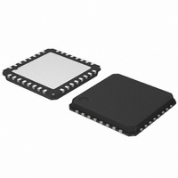
AMIS30623C623AG ON Semiconductor, AMIS30623C623AG Datasheet - Page 52

AMIS30623C623AG
Manufacturer Part Number
AMIS30623C623AG
Description
IC MOTOR DVR MICROSTP LIN 32NQFP
Manufacturer
ON Semiconductor
Type
Stepper Motor Driverr
Datasheet
1.AMIS30623C6239RG.pdf
(61 pages)
Specifications of AMIS30623C623AG
Applications
Stepper Motor Driver
Number Of Outputs
1
Current - Output
800mA
Voltage - Supply
6.5 V ~ 29 V
Operating Temperature
-40°C ~ 165°C
Mounting Type
Surface Mount
Package / Case
32-VSQFP
Product
Stepper Motor Controllers / Drivers
Operating Supply Voltage
5 V
Supply Current
10 mA
Mounting Style
SMD/SMT
Lead Free Status / RoHS Status
Lead free / RoHS Compliant
Voltage - Load
-
Lead Free Status / Rohs Status
Lead free / RoHS Compliant
Available stocks
Company
Part Number
Manufacturer
Quantity
Price
Company:
Part Number:
AMIS30623C623AG
Manufacturer:
ON Semiconductor
Quantity:
70
Company:
Part Number:
AMIS30623C623AG
Manufacturer:
ON Semiconductor
Quantity:
10 000
RunVelocity
LIN Master in order to put the motor in continuous motion
state. Note: in this mode (RunVelocity), the shaft bit has no
impact on the direction of movement.
RunVelocity corresponds to the following LIN writing frames (type #1).
Where:
SetDualPosition
in order to perform a positioning of the motor using two
different velocities. See Dual Positioning. After Dual
positioning the internal flag “Reference done” is set.
SetDualPosition corresponds to the following LIN writing frame with 0x3C identifier (type #4).
Where:
Table 57. RunVelocity WRITING FRAME TYPE #1
Table 58. SetDualPositioning WRITING FRAME TYPE #4
This command is provided to the circuit by the
(*) according to parity computation
Broad: If broad = ‘0’ all the stepper motors connected to the LIN bus will start continuous motion.
This command is provided to the circuit by the LIN master
Broad: If broad = ‘0’ all the circuits connected to the LIN bus will run the dual positioning
Vmax[3:0]: Max velocity for first motion
Vmin[3:0]: Min velocity for first motion and velocity for the second motion
Pos1[15:0]: First position to be reached during the first motion
Pos2[15:0]: Relative position of the second motion
Byte
Byte
0
1
2
3
0
1
2
3
4
5
6
7
8
9
Checksum
Checksum
Content
Identifier
Content
Identifier
Data 1
Data 2
Data 1
Data 2
Data 3
Data 4
Data 5
Data 6
Data 7
Data 8
Broad
Broad
Bit 7
Bit 7
1
0
1
*
Bit 6
Bit 6
0
*
Vmax[3:0]
http://onsemi.com
Bit 5
Bit 5
ID5
1
52
Note: The dynamic ID allocation has to be assigned to
‘General Purpose 2 Data bytes’ ROM pointer, i.e. ‘0000’.
The command is decoded only from the command data.
Note: Continuous LIN communication is required. If not,
Lost−LIN is detected and an autonomous motion will start.
See also LIN lost behavior.
Note: This sequence cannot be interrupted by another
positioning command.
Checksum over data
Bit 4
Bit 4
ID4
1
Pos1[15:8]
Pos2[15:8]
Structure
Structure
Pos1[7:0]
Pos2[7:0]
Checksum over data
CMD[6:0] = 0x17
CMD[6:0] = 0x08
AppCMD = 0x80
AD[6:0]
AD[6:0]
Bit 3
Bit 3
ID3
1
Bit 2
Bit 2
ID2
1
Vmin[3:0]
Bit 1
Bit 1
ID1
0
Bit 0
Bit 0
ID0
0


