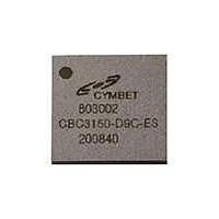
CBC3150-D9C-TR1 Cymbet Corporation, CBC3150-D9C-TR1 Datasheet

CBC3150-D9C-TR1
Specifications of CBC3150-D9C-TR1
CBC3150-D9C-TR1
Available stocks
Related parts for CBC3150-D9C-TR1
CBC3150-D9C-TR1 Summary of contents
Page 1
... EnerChip voltage to V The EnerChip CC also has energy storage protection such as: circuitry to enable thousands of recharge cycles. The CBC3150 is a 20-pin Dual Flat No- lead (DFN) package, available in tubes, trays, or tape- and-reel for use with automatic insertion equipment DFN SMT Package ...
Page 2
... EnerChip CC needs to be modified. The output impedance is dictated by 1/fC, where f is the frequency of oscillation (typically 100kHz) and C is the capacitor value (typically 0.1µF). GND is system ground. Figure 2: EnerChip CC CBC3150 Internal Block Diagram ©2009-2010 Cymbet Corporation • Tel: +1-763-633-1780 • www.cymbet.com DS-72-03 Rev B 3 ...
Page 3
... VCHG ENABLE RESET CP CN Figure 3: EnerChip CC CBC3150 Package Pin-out ©2009-2010 Cymbet Corporation • Tel: +1-763-633-1780 • www.cymbet.com DS-72-03 Rev B Label V Positive EnerChip Terminal - Tie to Pin 4 BAT V OUT EnerChip Charge Voltage - Tie to Pin 1 and/or Optional CHG ENABLE V Mode Select for Backup Switchover Threshold ...
Page 4
... Variable - see App. Note 1025 Non-recoverable Recoverable - - Charge cycle 2 Charge cycle 1000 5000 10% depth-of-discharge 1000 50% depth-of discharge 2500 10% depth-of-discharge 500 50% depth-of-discharge Charge cycle 2 Charge cycle 1000 100µA discharge; 25°C EnerChip Discharge Characteristics EnerChip CC CBC3150 TYPICAL MAX 6 +0 4.3 - 4 +0.3 OUT - 6 ...
Page 5
... OUT OUT CONDITION V rising from 2. <10µs V falling from 3. <100ns V =GND MODE MODE MODE DD V =GND MODE HYST MODE DD EnerChip CC CBC3150 MIN MAX UNITS - 3.5 µA - 6.0 µ µ µ MIN MAX UNITS V - 0.5 - Volts DD - 0.5 Volts ...
Page 6
... BAT 20mV below V BATCO I =1µA OUT I =1mA OUT V =4.1V BAT V =4.1V BAT OUT - pin is floating. Size the holding capacitor accordingly. OUT EnerChip CC CBC3150 MIN MAX UNITS 60 80 µ µs - 120 KHz (1) 150 300 Ω 4.075 4.125 V -2.0 -2.4 mV/º ...
Page 7
... Important timing diagrams for the EnerChip CC relationship between EnerChip Switchover Timing and EnerChip Disconnect from Load Timing are shown in Figure 4. V reset Figure 4: EnerChip CC Switchover and Disconnect Timing Diagrams ©2009-2010 Cymbet Corporation • Tel: +1-763-633-1780 • www.cymbet.com DS-72-03 Rev B EnerChip CC CBC3150 Page ...
Page 8
... Timing diagrams for the EnerChip CC relationship between V becoming active are shown in Figure 5. Figure 5: Timing Diagrams for V ©2009-2010 Cymbet Corporation • Tel: +1-763-633-1780 • www.cymbet.com DS-72-03 Rev B EnerChip CC CBC3150 to RESET and ENABLE high to charge pump DD to RESET and Enable to Charge Pump Active. DD ...
Page 9
... EnerChip CC could flow, placing a parasitic load on the EnerChip that could dramatically reduce the effective backup operating time. The EnerChip CC supports 2 operational modes as shown in Figures 6 and 7. ©2009-2010 Cymbet Corporation • Tel: +1-763-633-1780 • www.cymbet.com DS-72-03 Rev B EnerChip CC CBC3150 is used to route during normal operation when main ON ...
Page 10
... Mode 1 Operation For use in 3.3 volt systems. The V switchover threshold at approximately 3.0 volts. Figure 6: CBC3150 Typical Circuit for Mode 1 Operation Mode 2 Operation Figure 7 shows the circuitry for user-selectable switchover threshold to a value between 2.5 and 5.0 volts. Use Figure 8 to determine the value of R1. To determine the amount of hysteresis from the EnerChip switchover threshold, use Figure 9 ...
Page 11
... Cymbet Corporation • Tel: +1-763-633-1780 • www.cymbet.com DS-72-03 Rev B Ratio 0.3 0.4 0.5 0.6 0.7 0.8 0.9 R2/R1 Ratio Figure 8: Mode 2 Resistor Selection Graph Hysteresis in Battery Switchover Threshold Voltage vs. R2/R1 Ratio R2/R1 Ratio EnerChip CC CBC3150 Trip point 1 1.1 Hysteresis 1 1.1 Page ...
Page 12
... Adding Power and Energy Capacity with Parallel EnerChips In some applications, additional energy storage capacity might be needed. The schematic in Figure 11 shows how multiple EnerChips can be supported in parallel by a single EnerChip CC CBC3150. Note that C be increased by 0.1µF for every additional EnerChip. Figure 11: EnerChip CC Providing Power Management for Multiple EnerChips © ...
Page 13
... EnerChip CC CBC3150 PCB Layout Guidelines - Important Notice! There are several PCB layout considerations that must be taken into account when using the CBC3150: 1. All capacitors should be placed as close as possible to the EnerChip CC. The flying capacitor connections must be as short as possible and routed on the same layer the EnerChip CC is placed. ...
Page 14
... CBC3150 9mm x 9mm DFN Package Drawing and Dimensions Pin 1 ©2009-2010 Cymbet Corporation • Tel: +1-763-633-1780 • www.cymbet.com DS-72-03 Rev B EnerChip CC CBC3150 Notes: 1. Dimensions in millimeters. 2. Package dimensions do not include mold flash, protrusions, burrs or metal smearing. 3. Coplanarity applies to the exposed pad as well as the exposed terminals. Maximum coplanarity shall be 0 ...
Page 15
... Cymbet Applications Engineering. Figure 13: Implementing Energy Harvesting with the EnerChip CC Ordering Information EnerChip CC Part Number CBC3150-D9C CBC3150-D9C-TR1 CBC3150-D9C-TR5 CBC3150-D9C-WP Disclaimer of Warranties The information provided in this data sheet is provided “As Is” and Cymbet Corporation disclaims all representations or warranties of any ...


