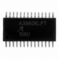
A3980KLP-T Allegro Microsystems Inc, A3980KLP-T Datasheet

A3980KLP-T
Specifications of A3980KLP-T
Related parts for A3980KLP-T
A3980KLP-T Summary of contents
Page 1
Automotive DMOS Microstepping Driver with Translator Features and Benefits ▪ Typical application up to ± output rating ▪ Low R outputs, 0.67 Ω source, 0.54 Ω sink typical DS(ON) ▪ Automatic current decay mode detection/selection ▪ 3.0 ...
Page 2
... A3980 Selection Guide Part Number Packing A3980KLPTR-T 4000 pieces per reel Absolute Maximum Ratings Characteristic Load Supply Voltage Logic Supply Voltage Logic Input Voltage Sense Voltage Reference Voltage Operating Ambient Temperature Maximum Junction Temperature Storage Temperature ESD Rating - Human Body Model ...
Page 3
A3980 5 V VDD V REF SENSE 1 DAC STEP DIR MS1 Translator MS2 RC1 PWM Latch Mixed Decay SLEEP ENABLE PFD PWM Latch RC2 Mixed Decay DAC SENSE 2 V ...
Page 4
A3980 ELECTRICAL CHARACTERISTICS Characteristics Output Drivers Load Supply Voltage Range 2 Output Leakage Current Output-On Resistance Body Diode Forward Voltage Motor Supply Current Logic Supply Current Logic Interface Logic Supply Voltage Range Input Low Voltage Input High Voltage Input Hysteresis ...
Page 5
A3980 ELECTRICAL CHARACTERISTICS Characteristics Current Control Blank Time Fixed Off Time Mixed Decay Trip Points Crossover Dead Time Recommended Reference Input Voltage Reference Input Current 2 Current Trip-Level Error 3 Thermal Protection Thermal Shutdown Thermal Shutdown Hysteresis Diagnostics Max V ...
Page 6
A3980 Logic Interface Timing Diagram STEP MS1, MS2, or DIR SLEEP Table 1. Microstep Resolution Truth Table MS1 MS2 Microstep Resolution Half Step L H Eighth Step H H Sixteenth Step Automotive DMOS Microstepping Driver t ...
Page 7
A3980 Table 3. Step Sequencing Settings Home microstep position at Step Angle 45º; DIR = H Phase 1 Full Half 1/8 1/16 Current Step Step Step Step [% I tripMax ] # # # # (%) 100.00 ...
Page 8
A3980 100.00 70.71 Phase 1 I OUT1B Direction = H (%) –70.71 –100.00 100.00 70.71 Phase 2 I OUT2B Direction = H (%) –70.71 –100.00 Figure 5. Full Step STEP 100.00 92.39 83.15 70.71 55.56 38.27 Phase 1 19.51 I ...
Page 9
A3980 STEP 100.00 95.69 88.19 83.15 77.30 70.71 63.44 55.56 47.14 38.27 29.03 19.51 Phase 1 9.8 I OUT1B 0.00 Direction = H –9.8 (%) –19.51 –29.03 –38.27 –47.14 –55.56 –63.44 –70.71 –77.30 –83.15 –88.19 –95.69 –100.00 100.00 95.69 88.19 ...
Page 10
A3980 Device Operation. The A3980 is a complete microstep- ping motor driver with a built-in translator for easy operation with minimal control lines designed to operate bipolar stepper motors in full-, half-, eighth-, and sixteenth-step modes. The currents ...
Page 11
A3980 as shown in table 3. In all other modes, V allowed to exceed 4 V, because the peak sense value can reach V ⁄ 100%. REF Fixed Off-Time. The internal PWM current control circuitry uses a one-shot ...
Page 12
A3980 Mixed Decay Operation. sequence, if the voltage on the PFD pin is between × × 0.6 V and 0. the full-bridge can operate mixed decay mode, as shown in fi gures 5 through 8. ...
Page 13
A3980 Shorted Load. A short across the load is detected by moni- toring the voltage across both the top and bottom FETs in each full-bridge. Short Fault Operation. Because motor capacitance may cause the measured voltages to show a fault ...
Page 14
A3980 The A3980 is a power circuit, therefore careful consider- ation must be given to power dissipation and the effects of high currents on interconnect and supply wiring. Power Dissipation. A fi rst order approximation of the power dissipation in ...
Page 15
A3980 The total dissipation for each of the four decay modes is the average power for the current ramp and the current decay portions of the PWM cycle. For slow decay, the current is rising for approximately 20% of the ...
Page 16
A3980 Current Sensing. To minimize inaccuracies caused by ground-trace IR drops in sensing the output current level, the current-sense resistors (R and R S1 independent ground return to the star ground point. This path should be as short as possible. ...
Page 17
A3980 Pin-out Diagram SENSE1 VBB1 DIR 3 OUT1A 4 PFD 5 RC1 6 AGND 7 ÷ 8 REF 8 RC2 9 Reg VDD VDD 10 OUT2A 11 MS2 12 MS1 13 SENSE2 14 VBB2 Automotive DMOS Microstepping ...
Page 18
A3980 Pacakge LP, 28-Pin TSSOP with Exposed Thermal Pad 9.70 ±0. 5.1 28X 0.10 C +0.05 0.25 0.65 –0.06 Copyright ©2003-2010, Allegro MicroSystems, Inc. Allegro MicroSystems, Inc. reserves the right to make, from time to ...


