SA07 Cirrus Logic Inc, SA07 Datasheet - Page 5
SA07
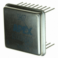
Manufacturer Part Number
SA07
Description
AMP PWM SW 40V 5A 18P DIP EL
Manufacturer
Cirrus Logic Inc
Series
Apex Precision Power™r
Datasheet
1.SA07.pdf
(7 pages)
Specifications of SA07
Mfg Application Notes
SAxx App Note 34
Applications
DC Motor Controller
Number Of Outputs
1
Current - Output
5A
Voltage - Load
5 V ~ 40 V
Voltage - Supply
10 V ~ 16 V
Operating Temperature
-55°C ~ 125°C
Mounting Type
Through Hole
Package / Case
18-DIP
For Use With
598-1457 - EVALUATION KIT FOR SA07
Lead Free Status / RoHS Status
Lead free / RoHS Compliant
Other names
598-1453
SA07
SA07
Available stocks
Company
Part Number
Manufacturer
Quantity
Price

Part Number:
SA07
Manufacturer:
APEX
Quantity:
20 000


The CLK OUT pin will normally be tied to the CLK IN pin. The clock is divided by two and applied to an RC network
which produces a ramp signal at the RAMP pin. An external clock signal can be applied to the CLK IN pin for syn-
chronization purposes. If a clock frequency lower than 1MHz is chosen an external capacitor must be tied to the
RAMP pin. This capacitor, which parallels an internal capacitor, must be selected so that the ramp oscillates 2.5
volts p-p with the lower peak 1.25 volts above ground.
BYPASSING
Adequate bypassing of the power supplies is required for proper operation. Failure to do so can cause erratic and
low efficiency operation as well as excessive ringing at the outputs. The Vs supply should be bypassed with at least
a 1µF ceramic capacitor in parallel with another low ESR capacitor of at least 10µF per amp of output current. Ca-
pacitor types rated for switching applications are the only types that should be considered. The bypass capacitors
must be physically connected directly to the power supply pins. Even one inch of lead length will cause excessive
ringing at the outputs. This is due to the very fast switching times and the inductance of the lead connection. The
bypassing requirements of the V
connected directly to the V
NOISE FILTERING
Switching noise can enter the SA07 through the INT OUT to +PWM connection. A wise precaution is to low pass
filter this connection. Adjust the pass band of the filter to 10 times the bandwidth required by the application. Keep
the resistor value to 100 ohms or less since this resistor becomes part of the hysteresis circuit on the pwm com-
parator.
PCB LAYOUT
The designer needs to appreciate that the SA07 combines in one circuit both high speed high power switching and
low level analog signals. Certain layout rules of thumb must be considered when a circuit board layout is designed
using the SA07:
1. Bypassing of the power supplies is critical. Capacitors must be connected directly to the power supply pins with
2. Make all ground connections with a star pattern at pin 7.
3. Beware of capacitive coupling between output connections and signal inputs through the parasitic capacitance
4. Do not run small signal traces between the pins of the output section (pins 11-16).
5. Do not allow high currents to flow into the ground plane.
6. Separate switching and analog grounds and connect the two only at pin 7 as part of the star pattern.
SA07U
very short lead lengths (well under 1 inch). Ceramic chip capacitors are best.
between layers in multilayer PCB designs.
P r o d u c t I n n o v a t i o n F r o m
CC
pin will suffice.
CC
supply are less stringent, but still necessary. A 0.1µF to 0.47µF ceramic capacitor
GENERAL
Please read Application Note 30 on "PWM Basics". Refer to Application
Note 1 "General Operating Considerations" for helpful information regard-
ing power supplies, heat sinking and mounting. Visit www.apexmicrotech.
com for design tools that help automate pwm filter design and heat sink
selection. The "Application Notes" and "Technical Seminar" sections con-
tain a wealth of information on specific types of applications. Information
on package outlines, heat sinks, mounting hardware and other accessories
are located in the "Packages and Accessories" section. Evaluation Kits are
available for most Apex product models, consult the "Evaluation Kit" section
for details. For the most current version of all Apex product data sheets, visit
www.apexmicrotech.com.
CLOCK CIRCUIT AND RAMP GENERATOR
The clock frequency is internally set to a frequency of approximately 1MHz.
SA07
Related parts for SA07
Image
Part Number
Description
Manufacturer
Datasheet
Request
R

Part Number:
Description:
Development Kit
Manufacturer:
Cirrus Logic Inc
Datasheet:
Part Number:
Description:
Development Kit
Manufacturer:
Cirrus Logic Inc
Datasheet:


Part Number:
Description:
High-efficiency PFC + Fluorescent Lamp Driver Reference Design
Manufacturer:
Cirrus Logic Inc
Datasheet:
Part Number:
Description:
Development Kit
Manufacturer:
Cirrus Logic Inc
Datasheet:
Part Number:
Description:
Development Kit
Manufacturer:
Cirrus Logic Inc
Datasheet:

Part Number:
Description:
Development Kit
Manufacturer:
Cirrus Logic Inc
Datasheet:
Part Number:
Description:
Development Kit
Manufacturer:
Cirrus Logic Inc
Datasheet:
Part Number:
Description:
Development Kit
Manufacturer:
Cirrus Logic Inc
Datasheet:
Part Number:
Description:
Development Kit
Manufacturer:
Cirrus Logic Inc
Datasheet:

Part Number:
Description:
EVALUATION BOARD FOR CS8427
Manufacturer:
Cirrus Logic Inc
Datasheet:

Part Number:
Description:
BOARD EVAL FOR CS8416 RCVR
Manufacturer:
Cirrus Logic Inc
Datasheet:

Part Number:
Description:
EVALUATION BOARD FOR CS8420
Manufacturer:
Cirrus Logic Inc
Datasheet:

Part Number:
Description:
KIT DEVELOPMENT EP9315 ARM9
Manufacturer:
Cirrus Logic Inc
Datasheet:

Part Number:
Description:
KIT DEVELOPMENT EP9302 ARM9
Manufacturer:
Cirrus Logic Inc
Datasheet: