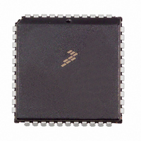
MC34920EI Freescale Semiconductor, MC34920EI Datasheet - Page 13

MC34920EI
Manufacturer Part Number
MC34920EI
Description
IC MOTOR DRIVER QUAD H 44-PLCC
Manufacturer
Freescale Semiconductor
Type
Quad Line Receiverr
Datasheet
1.MC34920EI.pdf
(29 pages)
Specifications of MC34920EI
Applications
DC Motor Driver, Stepper Motor Driver, H Bridge
Number Of Outputs
2
Current - Output
1.5A
Voltage - Supply
21 V ~ 42 V
Operating Temperature
-40°C ~ 125°C
Mounting Type
Surface Mount
Package / Case
44-PLCC
Operating Supply Voltage
10 V
Mounting Style
SMD/SMT
Lead Free Status / RoHS Status
Lead free / RoHS Compliant
Voltage - Load
-
Lead Free Status / Rohs Status
Lead free / RoHS Compliant
Available stocks
Company
Part Number
Manufacturer
Quantity
Price
Company:
Part Number:
MC34920EI
Manufacturer:
Freescale Semiconductor
Quantity:
10 000
Company:
Part Number:
MC34920EIR2
Manufacturer:
Freescale Semiconductor
Quantity:
10 000
Analog Integrated Circuit Device Data
Freescale Semiconductor
V1_FB
VCC
V2_FB
CS
SCLK
SDI
DRxPWM
DRx_MODE
The following inputs are through the Serial Input Register
V2_Enable
DR1_CURR_I1_PHASEA
DR1_CURR-I0_PHASEA
DR1_DIR_PH_A
DR1_CURR_I1_PHASEB
DR1_CURR_I0_PHASEB
DR1_DIR_PH_B
DR2_CURR_I1_PHASEA
DR2_CURR_I0_PHASEA
DR2_DIR_PH_A
DR2_CURR_I1_PHASEB
DR2_CURR_I0_PHASEB
DR2_DIR_PH_B
Name
Voltage feedback for the V1 regulator.
VCC power input for internal use. The 34920 accepts either 3.3 V ±10% or 5.0 V ±5% for its logic voltage.
Voltage feedback for the V2 regulator.
Serial input register chip select input. Active low.
Serial input register clock.
Serial input register serial data input.
PWM input for the DC motor driver for either Driver 1 or Driver 2.
Selects mode of each motor driver. Step = 1/ DC = 0.
Enable bit to turn on and off the V2 regulator and the motor drivers. When low (= logic [0]), the V2 regulator and
the motor drivers are turned off and the 34920 is placed in its lowest possible power state. V1 is not affected
by the Enable bit.
Second of two inputs that control the current level in the step motor Phase A winding (Driver 1 / Step Mode).
First of two inputs that control the current level in the step motor Phase A winding (Driver 1 / Step Mode).
Controls the direction of the current flow through Phase A of the step motor; i.e., logic [1] level causes
conventional current flow from DR1A1 to DR1B1 (Driver 1 / Step Mode).
Second of two inputs that control the current level in the step motor Phase B winding (Driver 1 / Step Mode).
First of two inputs that control the current level in the step motor Phase B winding (Driver 1/ Step Mode).
Controls the direction of the current flow through Phase B of the step motor. A logic [1] level causes
conventional current flow from DR1A2 to DR1B2 (Driver 1 / Step Mode).
Second of two inputs that control the current level in the step motor Phase A winding (Driver 2 / Step Mode).
One of two inputs that control the current level in the step motor Phase A winding (Driver 2 / Step Mode).
Controls the direction of the current flow through Phase A of the step motor. A logic [1] level causes
conventional current flow from DR2A1 to DR2B1 (Driver 2 / Step Mode).
Second of two inputs that control the current level in the step motor Phase B winding (Driver 2 / Step Mode).
One of two inputs that control the current level in the step motor Phase B winding (Driver 2 / Step Mode).
Controls the direction of the current flow through Phase B of the step motor. A logic [1] level causes
conventional current flow from DR2A2 to DR2B2 (Driver 2 / Step Mode).
Table 5. 34920 Input Specifications
Description
FUNCTIONAL INTERNAL BLOCK DESCRIPTION
FUNCTIONAL DESCRIPTION
34920
13


