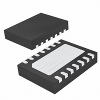
LTC4355CDE#TRPBF Linear Technology, LTC4355CDE#TRPBF Datasheet - Page 10

LTC4355CDE#TRPBF
Manufacturer Part Number
LTC4355CDE#TRPBF
Description
IC IDEAL DIODE-OR 14-DFN
Manufacturer
Linear Technology
Datasheet
1.LTC4355ISPBF.pdf
(20 pages)
Specifications of LTC4355CDE#TRPBF
Applications
-48V Dist Power Systems, AdvancedTCA ® Systems
Fet Type
N-Channel
Number Of Outputs
2
Internal Switch(s)
No
Delay Time - Off
300ns
Voltage - Supply
9 V ~ 80 V
Current - Supply
2mA
Operating Temperature
0°C ~ 70°C
Mounting Type
Surface Mount
Package / Case
14-DFN
Lead Free Status / RoHS Status
Lead free / RoHS Compliant
Delay Time - On
-
Available stocks
Company
Part Number
Manufacturer
Quantity
Price
APPLICATIONS INFORMATION
LTC4355
Loop Stability
The servo loop is compensated by the parasitic capaci-
tance of the power N-channel MOSFET. No further
compensation components are normally required. In
the case when a MOSFET with less than 1000pF gate
capacitance is chosen, a 1000pF compensation capacitor
connected across the gate and source pins might be
required.
Design Example
The following design example demonstrates the calculations
involved for selecting components in a 36V to 72V system
with 5A maximum load current (see Figure 2).
First, choose the N-channel MOSFET. The 100V, FDS3672
in the SO-8 package with R
good solution. The maximum voltage drop across it is:
The maximum power dissipation in the MOSFET is a mere:
10
ΔV = 5A • 22mΩ = 110mV
P = 5A • 110mV = 0.55W
V
V
IN1
IN2
= +48V
= +48V
GND
DS(ON)
12.7k
340k
R2
R1
= 22mΩ(max) offers a
12.7k
340k
R3
R4
F1
7A
F2
7A
Figure 2. 36V to 72V/5A Design Example
MON2
MON1
SET
IN1
FDS3672
GATE1
M1
LTC4355
GND
IN2
FDS3672
GATE2
M2
PANASONIC LN1351C
Next, select the resistive dividers that guarantee the
PWRFLT pins will not assert when the input supplies are
above 36V. The maximum V
maximum I
R1 = 12.7k. Then,
Use I
Adjust R2 down by 1% to 344k to account for its tolerance.
The next lower standard resistor value is R2 = 340k.
The LED D1, a Panasonic Green LN1351C, requires at least
1mA of current to fully turn on. Therefore, R5 is set to 33k
to accommodate the lowest input supply voltage of 36V.
FUSEFLT1
FUSEFLT2
PWRFLT1
PWRFLT2
VDSFLT
I
OUT
R2 =
=
R2
GREEN LEDs
12.7kΩ(−1%)
R2
=
to choose R2.
36V − 1.245V
V
1.245V
R1(MIN)
MONx(TH)
MONx(IN)
100μA
D1
33k
R5
D2
33k
R6
is 1μA. Choose a 1% tolerance resistor
+I
+ 1μA = 100μA
D3
MONx (TH)(MAX)
33k
R7
= 348kΩ
D4
33k
4355 F02
R8
MONx(TH)
D5
33k
R9
TO
LOAD
is 1.245V and the
4355fe


