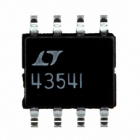
LTC4354IS8#PBF Linear Technology, LTC4354IS8#PBF Datasheet

LTC4354IS8#PBF
Specifications of LTC4354IS8#PBF
Available stocks
Related parts for LTC4354IS8#PBF
LTC4354IS8#PBF Summary of contents
Page 1
... Systems ■ –48V Distributed Power Systems ■ Computer Systems/Servers ■ Telecom Infrastructure ■ Optical Networks , LT, LTC and LTM are registered trademarks of Linear Technology Corporation. All other trademarks are the property of their respective owners. U TYPICAL APPLICATIO –48V Diode-OR –48V_RTN 12k V CC LTC4354 ...
Page 2
LTC4354 ABSOLUTE AXI U RATI GS (Note 1) I (100µs duration) ............................................. 50mA CC Output Voltages GA, GB ....................................... –0. FAULT .................................................... –0. Input Voltages DA, DB .................................................. –0.3V to 80V Input Current ...
Page 3
ELECTRICAL CHARACTERISTICS temperature range, otherwise specifications are at T SYMBOL PARAMETER V Internal Shunt Regulator Voltage Z ∆V Internal Shunt Regulator Load Regulation Z V Operating Voltage Range Supply Current GATE Pins Output High ...
Page 4
LTC4354 W U TYPICAL PERFOR A CE CHARACTERISTICS Shunt Regulator Voltage vs Input Current 12.0 11.5 11.0 10.5 10 (mA) CC 4354 G01 Source Drain Sense Voltage vs Temperature ...
Page 5
CTIO S DA, DB (Pins 1, 8): Drain Voltage Sense Inputs. These pins sense source-drain voltage drop across the N-Chan- nel MOSFETs. An external resistor is recommended to protect these pins from transient voltages exceeding ...
Page 6
LTC4354 DIAGRA V – GATE U OPERATIO High availability systems often employ parallel-connected power supplies or battery feeds to achieve redundancy and enhance system reliability. ORing diodes have been a ...
Page 7
U U APPLICATIO S I FOR ATIO Input Power Supply The power supply for the device is derived from –48_RTN through an external current limiting resistor (R internal shunt regulator clamps the voltage at V 11V. A 1µF decoupling capacitor ...
Page 8
LTC4354 U U APPLICATIO S I FOR ATIO System Power Supply Failure LTC4354 automatically supplies load current from the system supply with the more negative input potential. If this supply is shorted to the return side, a large reverse current ...
Page 9
U U APPLICATIO S I FOR ATIO The worst case power dissipation in R − 315 . Choose a 12k 0.5W resistor or use ...
Page 10
LTC4354 U U APPLICATIO S I FOR ATIO –48V_RTN V = –48V –48V B GND V = –12V –12V –36V to –72V/20A High Current with Parallel FETs R IN1 10k ...
Page 11
... MOLD FLASH OR PROTRUSIONS SHALL NOT EXCEED .006" (0.15mm) Information furnished by Linear Technology Corporation is believed to be accurate and reliable. However, no responsibility is assumed for its use. Linear Technology Corporation makes no represen- tation that the interconnection of its circuits as described herein will not infringe on existing patent rights. ...
Page 12
... Hot Swap Controller with Sequencer LT4351 MOSFET Diode-OR Controller LTC4412 Low Loss PowerPath™ Controller in ThinSOT™ Hot Swap, PowerPath and ThinSOT are trademarks of Linear Technology Corporation. Linear Technology Corporation 12 1630 McCarthy Blvd., Milpitas, CA 95035-7417 (408) 432-1900 FAX: (408) 434-0507 ● ...


