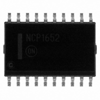
NCP1652DWR2G ON Semiconductor, NCP1652DWR2G Datasheet - Page 32

NCP1652DWR2G
Manufacturer Part Number
NCP1652DWR2G
Description
IC PFC CONTROLLER CCM/DCM 20SOIC
Manufacturer
ON Semiconductor
Datasheet
1.NCP1652DR2G.pdf
(34 pages)
Specifications of NCP1652DWR2G
Mode
Continuous Conduction (CCM), Discontinuous Conduction (DCM)
Frequency - Switching
100kHz
Current - Startup
5.62mA
Voltage - Supply
9.3 V ~ 20 V
Operating Temperature
-40°C ~ 125°C
Mounting Type
Surface Mount
Package / Case
20-SOIC (7.5mm Width)
Switching Frequency
20 KHz to 250 KHz
Maximum Operating Temperature
+ 125 C
Mounting Style
SMD/SMT
Minimum Operating Temperature
- 40 C
Lead Free Status / RoHS Status
Lead free / RoHS Compliant
Other names
NCP1652DWR2GOSTR
pull−up current source is always on and a 100 mA (typical)
pull−down current source is enabled once the Latch−Off pin
voltage reaches 3.5 V (typical). This effectively clamps the
Latch−Off pin voltage at 3.5 V. A minimum pull−up or
pull−down current of 50 mA is required to overcome the
internal current sources and latch the controller. The
facilitate design of the NCP1652 and reduce development
cycle time. The design tool can be downloaded at
www.onsemi.com.
†For information on tape and reel specifications, including part orientation and tape sizes, please refer to our Tape and Reel Packaging
ORDERING INFORMATION
Specifications Brochure, BRD8011/D.
NCP1652DWR2G
NCP1652DR2G
NCP1652ADR2G
The Latch−Off pin is clamped at 3.5 V. A 50 mA (typical)
ON Semiconductor provides an electronic design tool,
Device
Figure 70. Relationship Between the Latch−Off, V
V
Latch−Off
V
latch(high)
latch(low)
V
V
CC(on)
CC(off)
OUTA
OUTB
V
APPLICATION INFORMATION
CC
Latch−Off
Latch−Off
http://onsemi.com
SO−20 WB
(Pb−Free)
(Pb−Free)
(Pb−Free)
Package
SO−16
SO−16
32
Last OUTB Pulase
Latch−Off input features a 50 ms (typical) filter to prevent
latching the controller due to noise or a line surge event.
V
The controller exits the latch mode once power to the system
is removed and V
determine most of the system parameters of a single PFC
stage The tool evaluates the power stage as well as the
frequency response of the system.
CC(on)
The startup circuit continues to cycle V
The electronic design tool allows the user to easily
and V
CC
CC(off)
, OUTA and OUTB
CC
t
t
t
t
drops below V
while the controller is in latch mode.
1000 / Tape & Reel
2500 / Tape & Reel
2500 / Tape & Reel
Shipping
CC(reset)
†
.
CC
between


