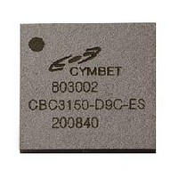
CBC3150-D9C-TR5 Cymbet Corporation, CBC3150-D9C-TR5 Datasheet - Page 11

CBC3150-D9C-TR5
Manufacturer Part Number
CBC3150-D9C-TR5
Description
IC BATT SOLID ST ENERCHIP 20DFN
Manufacturer
Cymbet Corporation
Series
EnerChip™ CCr
Specifications of CBC3150-D9C-TR5
Voltage - Output
3.3V
Capacity
50µAh
Operating Temperature
-20°C ~ 70°C
Package / Case
20-DFN
Output Voltage
3.3 V
Termination Style
SMD/SMT
Battery Cell Size
9 mm x 9 mm
For Use With
859-1003 - INDUCTIVE CHARGING EVAL KIT859-1001 - ENERCHIP CC EVAL KIT
Lead Free Status / RoHS Status
Lead free / RoHS Compliant
EnerChip charging and backup power switchover threshold for 2.5 to 5.5 volt operation is selected by changing
the value of R2 (see Figure 7). To determine the backup switchover point, set the value of R1 to 200kΩ and
choose the value of R2 according to Figure 8. For example, to set a 3.0V trip point: If R1=200 kΩ then R2 = R1
x 0.72 = 144kΩ. Figure 7 shows a Mode 2 circuit with standard value resistors of 200kΩ and 143kΩ.
To determine the backup switchover hysteresis for Mode 2 operation, use Figure 9.
DS-72-03 Rev B
©2009-2010 Cymbet Corporation • Tel: +1-763-633-1780 • www.cymbet.com
6
5
4
3
2
1
0
0.1
0.09
0.08
0.07
0.06
0.05
0.04
0.03
0.02
0.01
Figure 9: Mode 2 Hysteresis as a Function of R2/R1
Battery Switchover Threshold Voltage vs. R2/R1
0
0.1 0.2 0.3 0.4 0.5 0.6 0.7 0.8 0.9
0.2
Figure 8: Mode 2 Resistor Selection Graph
Hysteresis in Battery Switchover Threshold
0.3
0.4
Voltage vs. R2/R1 Ratio
0.5
R2/R1 Ratio
R2/R1 Ratio
0.6
Ratio
0.7
0.8
0.9
1
1
1.1
EnerChip CC CBC3150
1.1
Hysteresis
Trip point
Page 11 of 15


