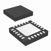
LM26480SQ-AA/NOPB National Semiconductor, LM26480SQ-AA/NOPB Datasheet - Page 22

LM26480SQ-AA/NOPB
Manufacturer Part Number
LM26480SQ-AA/NOPB
Description
IC REG BUCK/LDO DUAL 1.5A 24LLP
Manufacturer
National Semiconductor
Specifications of LM26480SQ-AA/NOPB
Applications
Processor
Voltage - Supply
2.8 V ~ 5.5 V
Operating Temperature
-40°C ~ 85°C
Mounting Type
Surface Mount
Package / Case
24-LLP
Operating Temperature (max)
85C
Operating Temperature (min)
-40C
Pin Count
24
Mounting
Surface Mount
Package Type
LLP EP
Case Length
4mm
Screening Level
Industrial
For Use With
LM26480SQ-AAEV - BOARD EVALUATION LM26480SQ-AA
Lead Free Status / RoHS Status
Lead free / RoHS Compliant
Current - Supply
-
Lead Free Status / Rohs Status
Compliant
Other names
LM26480SQ-AATR
Available stocks
Company
Part Number
Manufacturer
Quantity
Price
Company:
Part Number:
LM26480SQ-AA/NOPB
Manufacturer:
TI
Quantity:
3 400
Part Number:
LM26480SQ-AA/NOPB
Manufacturer:
NS/国半
Quantity:
20 000
www.national.com
OUTPUT INDUCTORS & CAPACITORS FOR SW1 AND
SW2
There are several design considerations related to the selec-
tion of output inductors and capacitors:
•
•
•
•
•
The LM26480 has been optimized for use with nominal values
2.2 µH and 10 µF. If other values are needed for the design,
please contact National Semiconductor sales with any con-
cerns.
INDUCTOR SELECTION FOR SW1 AND SW2
A nominal inductor value of 2.2 µH is recommended. It is im-
portant to guarantee the inductor core does not saturate
during any foreseeable operational situation.
Care should be taken when reviewing the different saturation
current ratings that are specified by different manufacturers.
Saturation current ratings are typically specified at 25ºC, so
ratings at maximum ambient temperature of the application
should be requested from the manufacturer.
There are two methods to choose the inductor saturation cur-
rent rating:
Recommended method:
The best way to guarantee the inductor does not saturate is
to choose an inductor that has saturation current rating
greater than the maximum LM26480 current limit of 2.4A. In
this case the device will prevent inductor saturation.
SUGGESTED INDUCTORS AND THEIR SUPPLIERS
Note: Inductor Current Saturation values are estimates; inductor manufacturer should be contacted for guaranteed values.
OUTPUT CAPACITOR SELECTION FOR SW1 AND SW2
A ceramic output capacitor of 10 µF, 6.3V is recommended
with an ESR of less than 500 mΩ.
Output ripple can be estimated from the vector sum of the
reactive (Capacitor) voltage component and the real (ESR)
voltage component of the output capacitor.
V
V
V
The output capacitor needs to be mounted as close as pos-
sible to the output pin of the device. For better temperature
DO3314-222MX
LPO3310-222MX
ELL6PG2R2N
ELC6GN2R2N
CDRH2D14NP-2R2NC
COUT
ROUT
PPOUT
Load transient response;
Stability;
Efficiency;
Output ripple voltage; and
Over-current ruggedness.
:
:
:
Estimated reactive output ripple
Estimated real output ripple
Estimated peak-to-peak output ripple
Model
Coilcraft
Coilcraft
Panasonic
Panasonic
Sumida
Vendor
22
Dimensions (mm)
Alternate method:
If the recommended approach cannot be used, care must be
taken to guarantee that the saturation current is greater than
the peak inductor current:
I
I
I
I
V
V
L:
F:
D:
EFF:
I
transients, startup, high temperature, worst case conditions,
etc.
performance, X7R or X5R types are recommended. DC bias
characteristics of ceramic capacitors must be considered
when selecting case sizes like 0805 and 0603.
DC bias characteristics vary from manufacturer to manufac-
turer and by case size. DC bias curves should be requested
from them as part of the capacitor selection process. ESR is
typically higher for smaller packages.
The output filter capacitor smooths out current flow from the
inductor to the load, helps maintain a steady output voltage
during transient load changes and reduces output voltage
ripple. These capacitors must be selected with sufficient ca-
pacitance and sufficiently low ESR to perform these functions.
Note that the output voltage ripple is dependent on the induc-
tor current ripple and the equivalent series resistance of the
output capacitor (ESR
dent as well as temperature dependent. The R
calculated with the applicable switching frequency and ambi-
ent temperature.
SAT
LPEAK
OUTMAX
RIPPLE
SAT
OUT
IN
3.3 x 3.3 x 1.4
6.0 x 6.0 x 2.0
6.0 x 6.0 x 1.5
3.2 x 3.2 x 1.5
3.3 x 3.3 x 1
:
:
may not be exceeded during any operation, including
:
:
:
: Maximum average inductor current
Inductor saturation current at operating tempera-
ture
Peak inductor current during worst case conditions
Peak-to-Peak inductor current
Output voltage
Input voltage
Inductor value in Henries at I
Switching frequency, Hertz
Estimated duty factor
Estimated power supply efficiency
COUT
DCR (max)
200 mΩ
150 mΩ
37 mΩ
53 mΩ
94 mΩ
). ESR
COUT
30040471
OUTMAX
is frequency depen-
I
SATURATION
ESR
≈
≈
≈
≈
≈
1.8A
1.3A
2.2A
1.9A
1.5A
should be


