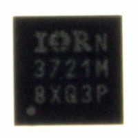
IR3721MTRPBF International Rectifier, IR3721MTRPBF Datasheet - Page 9

IR3721MTRPBF
Manufacturer Part Number
IR3721MTRPBF
Description
IC POWER SUPPLY MONITOR 10-DFN
Manufacturer
International Rectifier
Series
TruePower™r
Datasheet
1.IR3721MTRPBF.pdf
(16 pages)
Specifications of IR3721MTRPBF
Applications
Power Supply Monitor
Voltage - Supply
3.135 V ~ 3.465 V
Current - Supply
350µA
Operating Temperature
0°C ~ 125°C
Mounting Type
Surface Mount
Package / Case
10-DFN
Quiescent Current
450µA
Bandwidth
589kHz
Sensor Case Style
DFN
No. Of Pins
10
Supply Voltage Range
3.135V To 3.465V
Operating Temperature Range
0°C To +125°C
Filter Terminals
SMD
Rohs Compliant
No
Accuracy %
2.5%
Package
10 Lead 3x3 DFN
Static Accuracy
2.5% @ 65oC
Vk Range
0.5V - 1.8V
Vcs Range
5mV - 150mV
Bias Supply Voltage
+3.3V +/-5%
Junction Temperature
0oC to 125oC
Pbf
Yes
Lead Free Status / RoHS Status
Lead free / RoHS Compliant
Voltage - Input
-
Other names
IR3721MTRPBFTR
Available stocks
Company
Part Number
Manufacturer
Quantity
Price
Part Number:
IR3721MTRPBF
Manufacturer:
IR
Quantity:
20 000
COMPONENT SELECTION GUIDELINES
Use a 0.1 μF, 6.3V, X7R ceramic bypass capacitor
from VDD to GND and from VK to GND.
Filter the DI output with an RC filter to give a stable
analog representation of the current or power. Some
of the DI source resistance of this filter is internal to
the IR3721 and specified in the electrical
specifications table. Add twenty thousand to fifty
thousand additional ohms externally to minimize
resistance variation. As the DI source resistance
increases beyond these guidelines, the voltage
measurement error caused by non-ideal voltmeter
conductance will increase.
Select a filter capacitor that limits 512 kHz sampling
frequency ripple to an acceptable value. Sampling
frequency ripple will appear as an error, but can be
reduced 20 dB for each decade that the filter corner
frequency is below 512 kHz. Select a capacitor value
that achieves the desired balance between low
sampling frequency ripple and adequate bandwidth.
Resistor current sensing
For resistor current sensing select a precision resistor
for R
in the Electrical Specifications table, such as 25.5kΩ
and 1% tolerance.
Next, select a shunt resistor that will provide the most
current sensing voltage while also considering the
allowable power dissipation limitations. The DI output
will saturate to the VK voltage when full scale current
I
maximum current sensing voltage range is 5 to 150
mV. Maximum sensing voltages less than 5 mV will
cause comparator input offset voltage errors to
dominate, and voltages larger than 150 mV will cause
comparator leakage current, I
Select R
resistor from (R
accommodate full scale current I
Bypass VCS to VO with capacitor C
this capacitor limits the bandwidth, but is required
because it is the integrator of the delta sigma
modulator. Consider selecting the value of C
place a filter corner frequency at 5 kHz, which will
reduce sampling ripple by 40 dB.
DCR current sensing
Select an R
45.3kΩ. Consider the R
current sensing.
Page 9 of 16
FS
flows through this shunt. Recommended
T
inside the R
CS2
T
to be the next higher standard value
network resistance between 20kΩ and
SHUNT
T
resistance range limits specified
·I
FS
T
·R
network of Figure 5 for DCR
T
) / V
CS
RT
, errors to dominate.
FS
in order to
.
CS2
. The value of
www.irf.com
CS2
to
Figure 5 R
The resistance of the network above at 25°C, R
is 37.58kΩ. Over temperature R
copper resistance, DCR(25)·(1+(T-25)·0.0039),
divided by (DCR(25)·( R
results, and plotted as nominal error in Figure 6.
Figure 6 Nominal error vs. Temperature
Note that the error due to temperature compensation
at 25°C is zero, assuming ideal R
other temperatures the results are over or under
reported by the factor in percent indicated.
Proceed to calculate R
R
Again, I
voltage establishing the current in R
Estimate the capacitance C
equation.
15.0 kΩ, 1%
CS1
-1%
-2%
-3%
-4%
-5%
5%
4%
3%
2%
1%
0%
plus R
0
FS
is full scale current and V
T
R
CS2
network
SUM
, as follows.
20
26.1 kΩ, 1%
=I
FS
2.00 kΩ, 1%
Murata Thermistor
NCP15WB473F03RC
47 kΩ, 1%
·DCR(25) ·R
SUM
Temperature [°C]
40
T
(25)) to normalize the
, defined as the sum of
CS1
with the following
T
T
(T) is multiplied by
60
(25) / V
T
components. At
RT
T
DATA SHEET
.
is the reference
IR3721
RT
09/15/08
80
T
(25),
100


