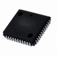
CS82C37AZ Intersil, CS82C37AZ Datasheet - Page 11

CS82C37AZ
Manufacturer Part Number
CS82C37AZ
Description
IC CMOS DMA CONTROLLER 44PLCC
Manufacturer
Intersil
Datasheet
1.CS82C37AZ.pdf
(24 pages)
Specifications of CS82C37AZ
Applications
CMOS DMA Controller
Voltage - Supply
4.5 V ~ 5.5 V
Current - Supply
2mA
Operating Temperature
0°C ~ 70°C
Mounting Type
Surface Mount
Package / Case
44-PLCC
Lead Free Status / RoHS Status
Lead free / RoHS Compliant
Voltage - Input
-
Available stocks
Company
Part Number
Manufacturer
Quantity
Price
edge. Status Bits 4-7 are cleared upon RESET or Master
Clear.
Status Register
Software Commands
There are special software commands which can be
executed by reading or writing to the 82C37A. These
commands do not depend on the specific data pattern on the
data bus, but are activated by the I/O operation itself. On
read type commands, the data value is not guaranteed.
These commands are:
Clear First/Last Flip-Flop - This command is executed
prior to writing or reading new address or word count
information to the 82C37A. This command initializes the flip-
flop to a known state (low byte first) so that subsequent
accesses to register contents by the microprocessor will
address upper and lower bytes in the correct sequence.
Set First/Last Flip-Flop - This command will set the flip-flop
to select the high byte first on read and write operations to
address and word count registers.
Master Clear - This software instruction has the same effect
as the hardware Reset. The Command, Status, Request,
7 6 5 4 3 2 1 0
Read Status Register
Write Command Register
Read Request Register
Write Request Register
Read Command Register
Write Single Mask Bit
Read Mode Register
Write Mode Register
Set First/Last F/F
Clear First/Last F/F
Read Temporary Register
Master Clear
Clear Mode Reg. Counter
Clear Mask Register
Read All Mask Bits
Write All Mask Bits
OPERATION
11
1 Channel 0 has reached TC
1 Channel 1 has reached TC
1 Channel 2 has reached TC
1 Channel 3 has reached TC
1 Channel 0 request
1 Channel 1 request
1 Channel 2 request
1 Channel 3 request
FIGURE 4. SOFTWARE COMMAND CODES AND REGISTER CODES
BIT NUMBER
A3
1
1
1
1
1
1
1
1
1
1
1
1
1
1
1
1
A2
0
0
0
0
0
0
0
0
1
1
1
1
1
1
1
1
82C37A
Temporary Register - The Temporary register is used to
hold data during memory-to-memory transfers. Following the
completion of the transfers, the last byte moved can be read
by the microprocessor. The Temporary register always
contains the last byte transferred in the previous memory-to-
memory operation, unless cleared by a Reset or Master
Clear.
and Temporary registers, and Internal First/Last Flip-Flop
and mode register counter are cleared and the Mask register
is set. The 82C37A will enter the idle cycle.
Clear Mask Register - This command clears the mask bits
of all four channels, enabling them to accept DMA requests.
Clear Mode Register Counter - Since only one address
location is available for reading the Mode registers, an
internal two-bit counter has been included to select Mode
registers during read operation. To read the Mode registers,
first execute the Clear Mode Register Counter command,
then do consecutive reads until the desired channel is read.
Read order is channel 0 first, channel 3 last. The lower two
bits on all Mode registers will read as ones.
A1
0
0
0
0
1
1
1
1
0
0
0
0
1
1
1
1
A0
0
0
1
1
0
0
1
1
0
0
1
1
0
0
1
1
IOR
0
1
0
1
0
1
0
1
0
1
0
1
0
1
0
1
IOW
1
0
1
0
1
0
1
0
0
1
0
1
0
1
0
1
March 20, 2006
FN2967.2


