AD536AKDZ Analog Devices Inc, AD536AKDZ Datasheet - Page 11
AD536AKDZ
Manufacturer Part Number
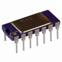
AD536AKDZ
Description
IC TRUE RMS/DC CONV 14-CDIP
Manufacturer
Analog Devices Inc
Datasheet
1.AD536AJHZ.pdf
(16 pages)
Specifications of AD536AKDZ
Current - Supply
1.2mA
Voltage - Supply
5.0V ~ 36V, ±3.0V ~ 18V
Mounting Type
Through Hole
Package / Case
14-CDIP (0.300", 7.62mm)
Accuracy %
0.2%
Bandwidth
45kHz
Supply Current
1.2mA
Power Dissipation Pd
500mW
Supply Voltage Range
5V To 36V
Digital Ic Case Style
DIP
No. Of Pins
14
Operating Temperature (max)
70C
Operating Temperature (min)
0C
Pin Count
14
Mounting
Through Hole
Screening Level
Commercial
Lead Free Status / RoHS Status
Lead free / RoHS Compliant
Lead Free Status / RoHS Status
Lead free / RoHS Compliant, Lead free / RoHS Compliant
Available stocks
Company
Part Number
Manufacturer
Quantity
Price
Company:

Part Number:
AD536AKDZ
Manufacturer:
Analog Devices Inc
Quantity:
135


THEORY OF OPERATION
The AD536A embodies an implicit solution of the rms equation
that overcomes the dynamic range as well as other limitations
inherent in a straightforward computation of rms. The actual
computation performed by the AD536A follows the equation
Figure 16 is a simplified schematic of the AD536A. Note that it
is subdivided into four major sections: absolute value circuit
(active rectifier), squarer/divider, current mirror, and buffer
amplifier. The input voltage (V
converted to a unipolar current (I
(A
the transfer function
The output current, I
mirror through a low-pass filter formed by R1 and the exter-
nally connected capacitor, C
much greater than the longest period of the input signal, then
I
I
the implicit rms computation. Thus,
V
The current mirror also produces the output current, I
equals 2I
4
3
IN
, which equals Avg[I
is effectively averaged. The current mirror returns a current
1
1
, A
I
I
V
4
4
2
NOTES
1. PINOUTS ARE FOR 14-LEAD DIP.
). I
= Avg [ I
= I
rms
25kΩ
R3
4
. I
1
I
2
drives one input of the squarer/divider, which has
/I
VOLTAGE-CURRENT
OUT
=
ABSOLUTE VALUE;
3
50kΩ
Avg
CONVERTER
A1
R4
I
12kΩ
2
can be used directly or can be converted to a
/ I
4
⎡
⎢
⎢
⎣
] = I
V
Figure 16. Simplified Schematic
V
+
12kΩ
4
IN
rms
, of the squarer/divider drives the current
4
I
], back to the squarer/divider to complete
2
rms
⎤
⎥
⎥
⎦
|V
A2
IN
|R
AV
–1
. If the R1 C
IN
I
), which can be ac or dc, is
1
1
) by the active rectifiers
ONE-QUADRANT
Q1
Q2
SQUARER/
0.2mA
DIVIDER
A3
FS
Q3
CURRENT MIRROR
AV
Q4
I
3
time constant is
I
2
4
Q5
C
R1
25kΩ
AV
BUF
I
IN
7
OUT
8
OUT
0.4mA
FS
I
REF
25kΩ
BUFFER
A4
25kΩ
, which
R2
COM
+V
–V
OUT
BUF
OUT
14
10
R
dB
Rev. D | Page 11 of 16
9
5
6
3
S
L
S
voltage with R2 and buffered by A4 to provide a low impedance
voltage output. The transfer function of the AD536A results in
the following:
The dB output is derived from the emitter of Q3 because the
voltage at this point is proportional to –log V
follower, Q5, buffers and level shifts this voltage so that the dB
output voltage is zero when the externally supplied emitter
current (I
CONNECTIONS FOR dB OPERATION
The logarithmic (or decibel) output of the AD536A is one of
its most powerful features. The internal circuit computing dB
works accurately over a 60 dB range. The connections for dB
measurements are shown in Figure 17.
Select the 0 dB level by adjusting R1 for the proper 0 dB reference
current (which is set to cancel the log output current from the
squarer/divider at the desired 0 dB point). The external op amp
provides a more convenient scale and allows compensation of
the +0.33%/°C scale factor drift of the dB output pin.
The temperature-compensating resistor, R2, is available online
in several styles from Precision Resistor Company, Inc., (Part
Number AT35 and Part Number ST35). The average temperature
coefficients of R2 and R3 result in the +3300 ppm required to
compensate for the dB output. The linear rms output is available
at Pin 8 on the DIP or Pin 10 on the header device with an output
impedance of 25 kΩ. Some applications require an additional
buffer amplifier if this output is desired.
For dB calibration,
1.
2.
3.
4.
Any other desired 0 dB reference level can be used by setting
V
proper gain automatically provides the correct temperature
compensation.
IN
and adjusting R1 accordingly. Note that adjusting R5 for the
V
Set V
Adjust R1 for dB output = 0.00 V.
Set V
Adjust R5 for dB output = −2.00 V.
OUT
REF
= 2 R2 × I rms = V
IN
IN
) to Q5 approximates I
= 1.00 V dc or 1.00 V rms.
= +0.1 V dc or 0.10 V rms.
IN
rms
3
.
IN
. The emitter
AD536A
Related parts for AD536AKDZ
Image
Part Number
Description
Manufacturer
Datasheet
Request
R

Part Number:
Description:
±1.7g Dual-Axis IMEMS Accelerometer Evaluation Board
Manufacturer:
Analog Devices Inc
Datasheet:

Part Number:
Description:
Inertial Sensor Evaluation System
Manufacturer:
Analog Devices Inc
Datasheet:
Part Number:
Description:
Manufacturer:
Analog Devices Inc
Datasheet:
Part Number:
Description:
Manufacturer:
Analog Devices Inc
Datasheet:
Part Number:
Description:
Manufacturer:
Analog Devices Inc
Datasheet:
Part Number:
Description:
Manufacturer:
Analog Devices Inc
Datasheet:
Part Number:
Description:
Manufacturer:
Analog Devices Inc
Datasheet:
Part Number:
Description:
Manufacturer:
Analog Devices Inc
Datasheet:
Part Number:
Description:
Manufacturer:
Analog Devices Inc
Datasheet:
Part Number:
Description:
Manufacturer:
Analog Devices Inc
Datasheet:
Part Number:
Description:
Manufacturer:
Analog Devices Inc
Datasheet:
Part Number:
Description:
Manufacturer:
Analog Devices Inc
Datasheet:
Part Number:
Description:
Manufacturer:
Analog Devices Inc
Datasheet: