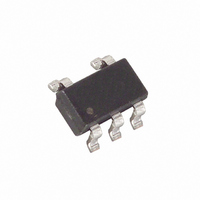
DS1775R1+T&R Maxim Integrated Products, DS1775R1+T&R Datasheet

DS1775R1+T&R
Specifications of DS1775R1+T&R
Related parts for DS1775R1+T&R
DS1775R1+T&R Summary of contents
Page 1
FEATURES § Temperature measurements require no external components § Measures temperatures from –55°C to +125°C. Fahrenheit equivalent is –67°F to 257°F § Thermometer accuracy is ±2.0°C § Thermometer resolution is configurable from bits (0.5°C to 0.0625°C ...
Page 2
ORDERING INFORMATION PART ADDR DS1775R+T&R 000 DS1775R+U 000 DS1775R/T&R 000 DS1775R-U 000 DS1775R1+T&R 001 DS1775R1+U 001 DS1775R1/T&R 001 DS1775R1-U 001 DS1775R2+T&R 010 DS1775R2+U 010 DS1775R2/T&R 010 DS1775R2-U 010 DS1775R3+T&R 011 DS1775R3+U 011 DS1775R3/T&R 011 DS1775R3-U 011 DS1775R4+T&R 100 DS1775R4+U 100 ...
Page 3
DETAILED PIN DESCRIPTION Table 1 PIN SYMBOL DESCRIPTION PIN 1 SCL Clock input/output pin for 2-wire serial communication port. This input should be tied to GND for standalone thermostat operation. PIN 2 GND Ground pin. PIN 3 O.S. Thermostat output ...
Page 4
DS1775 FUNCTIONAL BLOCK DIAGRAM Figure 1 OPERATION–Measuring Temperature The core of DS1775 functionality is its direct–to–digital temperature sensor. The DS1775 measures temperature through the use of an on–chip temperature measurement technique with an operating range from –55°C to +125°C. Temperature ...
Page 5
Temperature/Data Relationships Table MSb - TEMP +125°C +25.0625°C +10.125°C +0.5°C +0°C -0.5°C -10.125°C -25.0625°C -55°C OPERATION–Thermostat Control In its comparator operating mode, the DS1775 functions as a thermostat with ...
Page 6
O.S. OUTPUT TRANSFER FUNCTION Figure 2 Regardless of the mode chosen, the O.S. output is open–drain and the active state is set in the configuration register. The power–up default is active low. Refer to the “OPERATION–Programming” section for instructions in ...
Page 7
The pointer address must always proceed data in writing to a register, regardless of which address is currently selected. Please refer to the “2–Wire Serial Data Bus” section for details of the 2– wire bus protocol. Configuration Register Programming ...
Page 8
Thermometer Resolution Configuration Table Thermometer Resolution Thermostat Setpoints Programming The thermostat registers (T OS accessed by setting the DS1775 data pointer to the 03h location, and to the 02h ...
Page 9
SERIAL DATA BUS The DS1775 supports a bi–directional 2-wire bus and data transmission protocol. A device that sends data onto the bus is defined as a transmitter, and a device receiving data as a receiver. The device that controls ...
Page 10
DATA TRANSFER ON 2–WIRE SERIAL BUS Figure 4 Figure 5 details how data transfer is accomplished on the two–wire bus. Depending upon the state of the R/W bit, two types of data transfer are possible: 1. Data transfer from a ...
Page 11
SERIAL COMMUNICATION WITH DS1775 Figure ...
Page 12
ABSOLUTE MAXIMUM RATINGS* Voltage on VDD, Relative to Ground Voltage on any other pin, Relative to Ground Operating Temperature Storage Temperature Soldering Temperature * This is a stress rating only and functional operation of the device at these or any ...
Page 13
AC ELECTRICAL CHARACTERISTICS: 2–WIRE INTERFACE PARAMETER SCL clock frequency Bus free time between a STOP and START condition Hold time (repeated) START condition LOW period of SCL HIGH period of SCL Set-up time for a repeated START Data hold time ...
Page 14
TIMING DIAGRAMS Figure ...


