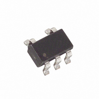
DS1775R1+T&R Maxim Integrated Products, DS1775R1+T&R Datasheet - Page 5

DS1775R1+T&R
Manufacturer Part Number
DS1775R1+T&R
Description
IC THERMOM/STAT DIG 001 SOT-23-5
Manufacturer
Maxim Integrated Products
Datasheet
1.DS1775RTR.pdf
(14 pages)
Specifications of DS1775R1+T&R
Function
Thermometer, Thermostat
Topology
ADC, Comparator, Register Bank
Sensor Type
Internal
Sensing Temperature
-55°C ~ 125°C
Output Type
I²C™/SMBus™
Output Alarm
Yes
Output Fan
No
Voltage - Supply
2.7 V ~ 5.5 V
Operating Temperature
-55°C ~ 125°C
Mounting Type
Surface Mount
Package / Case
SOT-23-5, SC-74A, SOT-25
Full Temp Accuracy
+/- 3 C
Digital Output - Bus Interface
Serial (2-Wire)
Digital Output - Number Of Bits
12 bit
Maximum Operating Temperature
+ 125 C
Minimum Operating Temperature
- 55 C
Lead Free Status / RoHS Status
Lead free / RoHS Compliant
Temperature/Data Relationships Table 2
OPERATION–Thermostat Control
In its comparator operating mode, the DS1775 functions as a thermostat with programmable hysteresis, as
shown in Figure 2. When the DS1775’s temperature meets or exceeds the value stored in the high
temperature trip register (T
output becomes active and stays active until the first time that the temperature falls below the temperature
stored in the low temperature trigger register (T
obtained. The DS1775 powers up in the comparator mode with T
used as a standalone thermostat (no 2–wire interface required) with those setpoints.
In the interrupt mode, the O.S. output will first become active following the programmed number of
consecutive conversions above T
shutdown mode or by reading any register (temperature, configuration, T
Following a clear, a subsequent fault can only occur if consecutive conversions fall below T
interrupt/clear process is thus cyclical (T
of multiple consecutive T
function. The same situation applies to multiple consecutive T
MSb
2
S
-1
+25.0625°C
-25.0625°C
+10.125°C
-10.125°C
+125°C
TEMP
+0.5°C
-0.5°C
-55°C
+0°C
2
2
-2
6
2
2
-3
5
OS
OS
) a consecutive number of times, as defined by the configuration register, the
violations will activate O.S., even if each fault is separated by a clearing
OS
2
2
(UNIT = °C)
. The fault can only be cleared by either setting the DS1775 in a
-4
DIGITAL OUTPUT
0111 1101 0000 0000
0000 1010 0010 0000
0000 1010 0010 0000
0000 0000 1000 0000
0000 0000 0000 0000
1111 1111 1000 0000
1111 0101 1110 0000
1110 0110 1111 0000
1100 1001 0000 0000
4
OS
, clear, T
(Binary)
2
0
3
5 of 14
HYST
HYST
). In this way, any amount of hysteresis may be
, clear, T
2
0
2
HYST
OS
events.
OS
, clear, T
2
0
1
=80°C and T
DIGITAL OUTPUT (Hex)
OS
HYST
LSb
, or T
2
0
0
, clear, ...). Only the first
HYST
7D00h
0A20h
F5E0h
E6F0h
C900h
HYST
FF80h
1910h
0080h
0000h
=75°C and can be
) on the device.
MSB
LSB
HYST
. This


