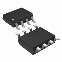
DS1626S+T&R Maxim Integrated Products, DS1626S+T&R Datasheet - Page 6

DS1626S+T&R
Manufacturer Part Number
DS1626S+T&R
Description
IC THERMOMETER/STAT DIG 8-SOIC
Manufacturer
Maxim Integrated Products
Datasheet
1.DS1626U.pdf
(12 pages)
Specifications of DS1626S+T&R
Function
Thermometer, Thermostat
Topology
ADC (Sigma Delta), Comparator, Register Bank
Sensor Type
Internal
Sensing Temperature
-55°C ~ 125°C
Output Type
3-Wire Serial
Output Alarm
Yes
Output Fan
No
Voltage - Supply
2.7 V ~ 5.5 V
Operating Temperature
-55°C ~ 125°C
Mounting Type
Surface Mount
Package / Case
8-SOIC (5.3mm Width), 8-SOP, 8-SOEIAJ
Full Temp Accuracy
+/- 2 C
Digital Output - Bus Interface
Serial (3-Wire)
Digital Output - Number Of Bits
12 bit
Maximum Operating Temperature
+ 125 C
Minimum Operating Temperature
- 55 C
Lead Free Status / RoHS Status
Lead free / RoHS Compliant
OPERATION—MEASURING TEMPERATURE
The DS1626/DS1726 measure temperature using a bandgap-based temperature sensor. A delta-sigma
analog-to-digital converter (ADC) converts the measured temperature to a digital value that is calibrated
in degrees Celsius; for Fahrenheit applications a lookup table or conversion routine must be used.
Communication with the DS1626/DS1726 is achieved through a 3-wire serial interface, and all data is
transmitted LSb first.
The DS1626/DS1726 can be programmed to take continuous temperature measurements (continuous
conversion mode) or to take single temperature measurements on command (one-shot mode). The
measurement mode is programmed by the 1SHOT bit in the configuration register as explained in the
CONFIGURATION REGISTER section of this data sheet. The 1SHOT bit is stored in EEPROM, so it can
be programmed prior to installation if desired. In continuous conversion mode, when a Start Convert T
command is issued the DS1626/DS1726 perform consecutive temperature measurements until a Stop
Convert T command is issued. In one-shot mode, the Start Convert T command causes one temperature
measurement to be taken and then the DS1626/DS1726 return to a low-power idle state.
The resolution of the DS1626/DS1726 digital temperature data is user-configurable to 9, 10, 11, or 12
bits, corresponding to temperature increments of 0.5°C, 0.25°C, 0.125°C, and 0.0625°C, respectively.
The resolution is set by the EEPROM R0 and R1 bits in the configuration register. Note that the
conversion time doubles for each additional bit of resolution.
After each temperature measurement and analog-to-digital conversion, the DS1626/DS1726 store the
measured temperature as a two’s complement number in the 12-bit temperature register (see Figure 4).
The sign bit (S) indicates if the temperature is positive or negative: for positive numbers S = 0 and for
negative numbers S = 1. The Read Temperature command provides user access to the temperature
register.
When the DS1626/DS1726 are configured for 12-bit resolution, all 12 bits of the temperature register will
contain temperature data. For 11-bit resolution, the 11 MSbs (bits 11 through 1) of the temperature
register will contain data and bit 0 will read out as 0. Likewise, for 10-bit resolution, the 10 MSbs (bits 11
through 2) will contain data, and for 9-bit the 9 MSbs (bits 11 through 3) will contain data, and all unused
LSbs will contain 0s. Since the DS1626/DS1726 transmit data LSb first, when reading data from the
temperature register, all 12 bits must be read in order to receive all MSbs of the measured data, regardless
of the conversion resolution. Table 2 gives examples of 12-bit resolution digital output data and the
corresponding temperatures.
Figure 4. TEMPERATURE, T
BIT 11
S
BIT 10
2
6
BIT 9
2
5
BIT 8
2
4
BIT 7
H
2
, and T
3
BIT 6
2
L
2
6 of 12
REGISTER FORMAT
BIT 5
2
1
BIT 4
2
0
BIT 3
2
-1
BIT 2
2
-2
BIT 1
DS1626/DS1726
2
-3
BIT 0
2
-4


