AD652AQ Analog Devices Inc, AD652AQ Datasheet - Page 13
AD652AQ
Manufacturer Part Number
AD652AQ
Description
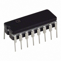
IV V-F CONVERTER SYNC 16-CDIP
Manufacturer
Analog Devices Inc
Type
Voltage to Frequencyr
Specifications of AD652AQ
Rohs Status
RoHS non-compliant
Frequency - Max
2MHz
Full Scale
±50ppm/°C
Linearity
±0.02%
Mounting Type
Through Hole
Package / Case
16-CDIP (0.300", 7.62mm)
Full Scale Range
1MHz To 2MHz
Linearity %
0.02%
Supply Voltage Range
± 6V To ± 18V
Digital Ic Case Style
DIP
No. Of Pins
16
Frequency Max
2MHz
Termination Type
Through Hole
Converter Function
VFC
Full Scale Frequency
2000
Power Supply Requirement
Single/Dual
Single Supply Voltage (max)
36V
Single Supply Voltage (min)
12V
Dual Supply Voltage (typ)
±15V
Dual Supply Voltage (min)
±6V
Dual Supply Voltage (max)
±18V
Operating Temperature (min)
-40C
Operating Temperature (max)
85C
Operating Temperature Classification
Industrial
Package Type
CDIP
Converter Type
Voltage to Frequency
Current, Quiescent Supply
±11 mA (Typ.)
Frequency Range
5 MHz (Typ.)
Input Impedance
20 Kiloohms
Number Of Pins
20
Temperature, Operating, Maximum
85 °C
Temperature, Operating, Minimum
-40 °C
Voltage, Range
±6 to ±18 V
Voltage, Supply
36 V
Filter Terminals
Through Hole
Rohs Compliant
No
Calibration Error Fs Typ
5%
Lead Free Status / Rohs Status
Not Compliant
Available stocks
Company
Part Number
Manufacturer
Quantity
Price
Company:

Part Number:
AD652AQ
Manufacturer:
TOSHIBA
Quantity:
670


The one-shot capacitor controls the pulse width of the
frequency output. The pulse is initiated by the rising edge of the
clock signal. The delay time between the rising edge of the clock
and the falling edge of the frequency output is typically 200 ns.
The width of the pulse is 5 ns/pF, and the minimum width is
about 200 ns with Pin 9 floating. If the one-shot period is
accidentally chosen longer than the clock period, the width of
the pulse defaults to equal the clock period. The one-shot can be
disabled by connecting Pin 9 to +V
pulse width is then equal to the clock period. The one-shot is
activated (Figure 18) by connecting a capacitor from Pin 9 to
+V
S
, −V
S,
or Digital Ground (+V
1
2
3
4
5
6
7
8
+V
S
20kΩ
SYNCHRONOUS
1
2
3
4
5
6
7
8
VOLTAGE-TO-
FREQUENCY
CONVERTER
20kΩ
AD652
1mA
SYNCHRONOUS
VOLTAGE-TO-
FREQUENCY
CONVERTER
Figure 17. One-Shot Disabled
Figure 18. One-Shot Enabled
AD652
1mA
REFERENCE
(+V
AND
S
S
5V
, –V
is preferred).
REFERENCE
AND
S
D
SHOT
S
(Figure 17); the output
ONE
Q
Q
, OR DIGITAL GND)
5V
FLOP
"D"
CK
D
SHOT
ONE
Q
Q
ANY AC GND
FLOP
"D"
CK
16
15
14
13
12
11
10
9
16
15
14
13
12
11
10
9
C
OS
Rev. C | Page 13 of 28
DIGITAL GROUND
Digital Ground can be at any potential between −V
(+V
grounds rather than stiff supplies. For example, in a small
isolated power circuit, often only a single supply is generated
and the ground is set by a divider tap. Such a ground cannot
handle the large currents associated with digital signals. With
the AD652 SVFC, it is possible to connect the Digital Ground to
–V
C
V
INT
–
+
IN
S
S
for a solid logic reference, as shown in Figure 19.
– 4 V). This can be very useful in systems with derived
+V
–V
S
S
1
2
3
4
5
6
7
8
20kΩ
SYNCHRONOUS
VOLTAGE-TO-
FREQUENCY
CONVERTER
AD652
1mA
Figure 19. Digital GND at −V
REFERENCE
AND
5V
D
SHOT
ONE
Q
Q
FLOP
"D"
CK
S
16
15
14
13
12
11
10
9
R
S
C
L
CLOCK
OS
and
AD652
5V
FREQ
OUT
Related parts for AD652AQ
Image
Part Number
Description
Manufacturer
Datasheet
Request
R

Part Number:
Description:
±1.7g Dual-Axis IMEMS Accelerometer Evaluation Board
Manufacturer:
Analog Devices Inc
Datasheet:

Part Number:
Description:
Inertial Sensor Evaluation System
Manufacturer:
Analog Devices Inc
Datasheet:
Part Number:
Description:
Manufacturer:
Analog Devices Inc
Datasheet:
Part Number:
Description:
Manufacturer:
Analog Devices Inc
Datasheet:
Part Number:
Description:
Manufacturer:
Analog Devices Inc
Datasheet:
Part Number:
Description:
Manufacturer:
Analog Devices Inc
Datasheet:
Part Number:
Description:
Manufacturer:
Analog Devices Inc
Datasheet:
Part Number:
Description:
Manufacturer:
Analog Devices Inc
Datasheet:
Part Number:
Description:
Manufacturer:
Analog Devices Inc
Datasheet:
Part Number:
Description:
Manufacturer:
Analog Devices Inc
Datasheet:
Part Number:
Description:
Manufacturer:
Analog Devices Inc
Datasheet:
Part Number:
Description:
Manufacturer:
Analog Devices Inc
Datasheet:
Part Number:
Description:
Manufacturer:
Analog Devices Inc
Datasheet: