NCP100SNT1G ON Semiconductor, NCP100SNT1G Datasheet
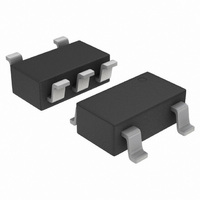
IC REG SHUNT PREC ADJ 1V SOT23-5

NCP100SNT1G

Manufacturer Part Number
NCP100SNT1G
Description
IC REG SHUNT PREC ADJ 1V SOT23-5
Manufacturer
ON Semiconductor
Datasheet

Specifications of NCP100SNT1G

Reference Type
Shunt, Adjustable
Voltage - Output
0.9 ~ 6 V
Tolerance
±2.6%
Number Of Channels
1
Current - Cathode
80µA
Current - Output
20mA
Operating Temperature
-40°C ~ 85°C
Mounting Type
Surface Mount
Package / Case
TSOT-23-5, TSOT-5, TSOP-5
Product
Voltage References
Topology
Shunt References
Output Voltage
0.9 V to 6 V
Initial Accuracy
1.7 %
Series Vref - Input Voltage (max)
7 V
Shunt Current (max)
20 mA
Maximum Operating Temperature
+ 85 C
Input Voltage
1 mV
Minimum Operating Temperature
- 40 C
Mounting Style
SMD/SMT
Shunt Current (min)
0.1 mA
Fixed / Adjust / Prog
Adjust
Output Voltage (max)
0.9 to 6V
Reference Voltage Accuracy (max)
1.7
Input Voltage (max)
7V
Operating Temp Range
-40C to 85C
Operating Temperature Classification
Industrial
Mounting
Surface Mount
Pin Count
5
Package Type
TSOP
Lead Free Status / RoHS Status
Lead free / RoHS Compliant
Voltage - Input
-
Temperature Coefficient
-
Current - Quiescent
-
Lead Free Status / Rohs Status
Lead free / RoHS Compliant
Other names
NCP100SNT1GOS
NCP100SNT1GOS
NCP100SNT1GOSTR

Available stocks

Company
Part Number
Manufacturer
Quantity
Price
Part Number:
NCP100SNT1G
Manufacturer:
ON Semiconductor
Quantity:
138 584
Part Number:
NCP100SNT1G
Manufacturer:
ON/安森美
Quantity:
20 000
NCP100
Sub 1.0 V Precision
Adjustable Shunt Regulator
programmable over a voltage range of 0.9 V to 6.0 V. This device
features a guaranteed reference accuracy of ±1.7% at 25°C and ±2.6%
over the entire temperature range of −40°C to 85°C. The NCP100
exhibits a sharp low current turn−on characteristic with a low dynamic
impedance of 0.20 W over an operating current range of 100 mA to
20 mA. These characteristics make this device an ideal replacement
for zener diodes in numerous application circuits that require a precise
low voltage reference. When combined with an optocoupler, the
NCP100 can be used as an error amplifier for controlling the feedback
loop in isolated low output voltage (2.3 V) switching power supplies.
This device is available in TO−92 and in an economical space saving
TSOP−5 package.
Features
Applications
© Semiconductor Components Industries, LLC, 2009
August, 2009 − Rev. 11
Reference
The NCP100 is a precision low voltage shunt regulator that is
Programmable Output Voltage Range of 0.9 V to 6.0 V
Voltage Reference Tolerance of ±1.7%
Sharp Low Current Turn−ON Characteristic
Low Dynamic Output Impedance of 0.2 W from 100 mA to 20 mA
Wide Operating Current Range of 80 mA to 20 mA
TO−92 and Space Saving TSOP−5 Package
This is a Pb−Free Device
Reference for Single Cell Alkaline, NiCD and NiMH Applications
Low Output Voltage (2.3 V) Switching Power Supply Error Amp
Battery Powered Consumer Products
Portable Test Equipment and Instrumentation
(R)
Figure 1. Symbol
Cathode (K)
Anode (A)
Reference
Figure 2. Representative Block Diagram
(R)
0.7 V
Cathode (K)
Anode (A)
1
†For information on tape and reel specifications,
NCP100SNT1G
NCP100ALPRPG
including part orientation and tape sizes, please
refer to our Tape and Reel Packaging Specifications
Brochure, BRD8011/D.
STRAIGHT LEAD
ALYWWG
1 2
XXXXX
XXXXX
BULK PACK
Device
3
G
Cathode
Anode
ORDERING INFORMATION
PIN CONNECTIONS AND
NC
MARKING DIAGRAM
http://onsemi.com
Pin 1. Reference
XXXXX = Specific Device Code
A
L
Y
WW
G
(Note: Microdot may be in either
location)
1
2
3
(Pb−Free)
(Pb−Free)
1
(Top View)
Package
TSOP−5
TAPE & REEL
2. Anode
3. Cathode
TO−92
AMMO PACK
BENT LEAD
2
RAB = Device Code
A
Y
W
G
3
Publication Order Number:
= Assembly Location
= Wafer Lot
= Year
= Work Week
= Pb−Free Package
= Assembly Location
= Year
= Work Week
= Pb−Free Package
5
4
3000 / Tape & Reel
2000 / Ammo Pack
TO−92 (TO−226)
Anode
Reference
LP SUFFIX
CASE 029
Shipping
SN SUFFIX
CASE 483
TSOP−5
NCP100/D
5
1

Related parts for NCP100SNT1G

NCP100SNT1G Summary of contents

Page 1

... STRAIGHT LEAD BULK PACK XXXXX XXXXX Cathode (K) ALYWWG 0.7 V Anode (A) Device NCP100SNT1G NCP100ALPRPG †For information on tape and reel specifications, including part orientation and tape sizes, please refer to our Tape and Reel Packaging Specifications Brochure, BRD8011/D. 1 http://onsemi.com TO−92 (TO−226) LP SUFFIX ...

Page 2

MAXIMUM RATINGS (T = 25°C, unless otherwise noted.) A Á Á Á Á Á Á Á Á Á Á Á Á Á Á Á Á Á Á Á Á Á Cathode to Anode Voltage (Note 1) Á Á Á Á ...

Page 3

ELECTRICAL CHARACTERISTICS Characteristic Á Á Á Á Á Á Á Á Á Á Á Á Á Á Á Á Á Á Á Reference Voltage ( mA, Figure 3) KA Á Á Á Á Á Á Á Á Á ...

Page 4

100 k REF Figure 3. General Test Circuit 110 100 0.1 mF 0.01 mF Figure 5. Test Circuit for Dynamic Impedance vs. ...

Page 5

25°C A Figure 3 10 5.0 0 −5.0 −10 −0.8 −0.6 −0.4 −0.2 0 0.2 0 CATHODE VOLTAGE (V) KA Figure 9. Cathode Current ...

Page 6

T = −40°C A 697 = 25°C = 70°C 696 50 100 150 200 I , CATHODE CURRENT (mA) K Figure 15. Reference Voltage vs. Cathode Current for 714 = 85°C 710 = 70°C ...

Page 7

The NCP100 is an adjustable shunt regulator similar to the industry standard 431−type regulators. Each device is laser trimmed at wafer probe to allow for tight reference accuracy and low reference voltage shift over the full operating temperature range of ...

Page 8

The circuit performs the same as the one in Figure 21 with the exception of the effects of R comp voltage across R also increases by: comp V comp + comp V effectively adjusts the NCP100 programmed ...

Page 9

out + V REF R2 V out min + 0 Figure 26. High Current Shunt Regulator AC Line Input UC3842 1/2 Opto + + - Figure 28. Offline Converter ...

Page 10

TO−92 EIA RADIAL TAPE ON REEL Symbol D Tape Feedhole Diameter D2 Component Lead Thickness Dimension F1, F2 Component Lead Pitch H Bottom of Component to Seating Plane H1 Feedhole Location H2A Deflection Left or Right Deflection ...

Page 11

PACKAGE DIMENSIONS SEATING K PLANE SEATING K PLANE TO−92 (TO−226) CASE 29−11 ISSUE AM ...

Page 12

... C 0.05 H *For additional information on our Pb−Free strategy and soldering details, please download the ON Semiconductor Soldering and Mounting Techniques Reference Manual, SOLDERRM/D. ON Semiconductor and are registered trademarks of Semiconductor Components Industries, LLC (SCILLC). SCILLC reserves the right to make changes without further notice to any products herein. SCILLC makes no warranty, representation or guarantee regarding the suitability of its products for any particular purpose, nor does SCILLC assume any liability arising out of the application or use of any product or circuit, and specifically disclaims any and all liability, including without limitation special, consequential or incidental damages. “ ...

Related keywords