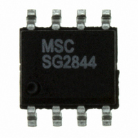
SG2844DM Microsemi Analog Mixed Signal Group, SG2844DM Datasheet - Page 11

SG2844DM
Manufacturer Part Number
SG2844DM
Description
IC PWM CURRENT MODE 8SOIC
Manufacturer
Microsemi Analog Mixed Signal Group
Datasheet
1.SG3845M.pdf
(12 pages)
Specifications of SG2844DM
Pwm Type
Current Mode
Number Of Outputs
1
Frequency - Max
500kHz
Duty Cycle
50%
Voltage - Supply
8.2 V ~ 30 V
Buck
Yes
Boost
No
Flyback
No
Inverting
No
Doubler
No
Divider
No
Cuk
No
Isolated
Yes
Operating Temperature
-25°C ~ 85°C
Package / Case
8-SOIC
Frequency-max
500kHz
Lead Free Status / RoHS Status
Lead free / RoHS Compliant
Available stocks
Company
Part Number
Manufacturer
Quantity
Price
Company:
Part Number:
SG2844DM
Manufacturer:
Microsemi
Quantity:
2 464
Copyright © 2000
Rev. 1.6c
The 1844/45 output stage can provide negative base current to
remove base charge of power transistor (Q
is accomplished by adding a capacitor (C
(R
The RC low-pass filter will eliminate the leading edge current spike
caused by parasitics of Power MOSFET.
1
). The resistor (R
»
FIGURE 14. — CURRENT SENSE SPIKE SUPPRESSION
R
SG1844/45
»
1
SG1844/45
V
| | R
FIGURE 16. — BIPOLAR TRANSISTOR DRIVE
C1
V
R
C
2
2
+
_
I
B
Pin numbers referenced are for 8-pin package and pin numbers in parenthesis are for 14-pin package.
7 (12)
1
) is to limit the base current during turn on.
V
C
7 (11)
6 (10)
5 (8)
3 (5)
7 (11)
6 (10)
5 (8)
3 (5)
V
CC
C
P R O D U C T D A T A B O O K 1 9 9 6 / 1 9 9 7
R
R
2
V
IN
1
C
Q1
R
) in parallel with a resistor
S
1
T Y P I C A L A P P L I C A T I O N C I R C U I T S
) for faster turn off. This
U R R E N T
P
V
C
R
C1
1
1
R O D U C T I O N
I
PK(MAX)
V
= 1.0V
IN
Q1
R
- M
S
R
I
PK
S
O D E
P W M C
D
A resistor (R
ringing caused by the MOSFET input capacitance and any inductance
in series with the gate drive. (Note: It is very important to have a
low inductance ground path to insure correct operation of the I.C.
This can be done by making the ground paths as short and as wide
as possible.)
Current transformers can be used where isolation is required
between PWM and Primary ground. A drive transformer is then
necessary to interface the PWM output with the MOSFET.
A T A
I
SG1844/45
PK
=
V (PIN 1) - 1.4
O N T R O L L E R
FIGURE 15. — MOSFET PARASITIC OSCILLATIONS
7 (12)
S
1
) in series with the MOSFET gate reduce overshoot and
3R
H E E T
FIGURE 17. — ISOLATED MOSFET DRIVE
SG1844/SG1845 Series
7 (11)
6 (10)
5 (8)
3 (5)
S
SG1844/45
V
CC
C
N
N
7 (12)
3 (5)
Boundary
Isolation
P
S
R
7 (11)
6 (10)
5 (8)
R
S
R
V
1
CC
N
V
S
IN
Q1
R
S
V
IN
Q1
N
P
+
0
+
_ 0
V
_
GS
50% DC
25% DC
Waveforms
11


