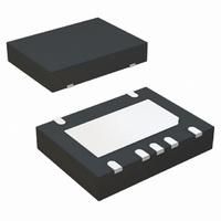
IR3629AMTRPBF International Rectifier, IR3629AMTRPBF Datasheet

IR3629AMTRPBF
Specifications of IR3629AMTRPBF
Related parts for IR3629AMTRPBF
IR3629AMTRPBF Summary of contents
Page 1
... General DC-DC Converters Fig. 1: Typical application Circuit ORDERING INFORMATION PKG PACKAGE DESIG DESCRIPTION M IR3629/IR3629AMPBF M IR3629/IR3629AMTRPBF 11/29/2007 IR3629/IR3629A MPbF WITH POWER GOOD OUTPUT Description The IR3629/IR3629A is a PWM controller designed for high performance synchronous Buck DC/DC applications. The IR3629/IR3629A drives DS(on) a pair of external N-MOSFETs using a fixed 600kHz (300kHz “ ...
Page 2
ABSOLUTE MAXIMUM RATINGS (Voltages referenced to GND) • Vcc Supply Voltage ................................................… -0.5V to 16V • Vc Supply Voltage …………………………………….. -0.5V to 30V • PGood ………………………………………………… -0.5V to 16V • Fb, Comp, SS ……………………..………………….. -0.3V to 3.5V • OCset ………………………………………………… ...
Page 3
Block Diagram Fig. 2: Simplified block diagram of the IR3629/IR3629A 11/29/2007 IR3629/IR3629A MPbF 3 ...
Page 4
Pin Description Pin Name 1 PGood Power Good status pin. Output is open collector. Connect a pull up resistor from this pin to Vcc. 2 Vcc This pin provides biasing voltage for the internal blocks of the IC. It also ...
Page 5
Recommended Operating Conditions Symbol Definition V Supply Voltage cc V Supply Voltage c T (Note1) Junction Temperature j Note1: The junction temperature for 5V application is 0 Electrical Specifications Unless otherwise specified, these specification apply over V Typical value are ...
Page 6
Parameter SYM Error Amplifier Input Bias Current I FB1 Input Bias Current I FB2 Source/Sink Current I(source/Sink) Transconductance gm Soft Start/SD Soft Start Current I SS Shutdown Output SD Threshold Over Current Protection OCSET Current I OCSET Hiccup Current I ...
Page 7
TYPICAL OPERATING CHARACTERISTICS Vfb(mV) 601.0 600.5 600.0 599.5 599.0 598.5 598.0 597.5 597.0 -40 - Temp[oC] Icc(static)(mA) 12.0 11.0 10.0 9.0 8.0 7.0 6.0 -40 - Temp[oC] Transconductance (gm)[mMHO] 1.5 ...
Page 8
Circuit Description THEORY OF OPEARTION Introduction The IR3629/29A is a voltage mode PWM synchronous controller and operates with a fixed 600kHz (300kHz for IR3629A) frequency, allowing the use of small external components. The output voltage is set by a feedback ...
Page 9
Soft-Start The IR3629/29A has a programmable soft-start to control the output voltage rise and limit the inrush current during start-up. To ensure correct start-up, sequence initiates when Vcc and Vc rise above their threshold and generate the Power On Ready ...
Page 10
Over-Current Protection The over current protection is performed by sensing current through the R DS(on) side MOSFET. This method enhances the converter’s efficiency and reduces cost by eliminating a current sense resistor. As shown in figure 7, an external resistor ...
Page 11
Application Information Design Example: The following example is a typical application for IR3629A. The application circuit is shown on page 18 V max ...
Page 12
Input Capacitor Selection The ripple current generated during the on time of upper the MOSFET should be provided by the input capacitor. The RMS value of this ripple is expressed by: = ∗ ∗ ( − ...
Page 13
Power MOSFET Selection The IR3629A uses two N-Channel MOSFETs per channel. The selection criteria to meet power transfer requirements are based on maximum drain-source voltage (V ), gate-source drive DSS voltage (V ), maximum output current, On- gs resistance R ...
Page 14
Feedback Compensation The IR3629A is a voltage mode controller. The control loop is a single voltage feedback path including error amplifier and error comparator. To achieve fast transient response and accurate output regulation, a compensation circuit is necessary. The goal ...
Page 15
To cancel one of the LC filter poles, place the zero before the LC filter resonant frequency pole π ...
Page 16
Based on the frequency of the zero generated by the output capacitor and its ESR versus crossover frequency, the compensation type can be different. The table below shows the compensation types and location crossover frequency. Compensator F vs. F ESR ...
Page 17
Programming the Current-Limit The Current-Limit threshold can be set by connecting a resistor (R ) from the drain of the SET low-side MOSFET to the OCSet pin. The resistor can be calculated by using equation (3). The R has a ...
Page 18
Fig.16: Application circuit for IR3629A 12Vin to 1.8Vout 11/29/2007 IR3629/IR3629A MPbF 18 ...
Page 19
PCB Metal and Components Placement The lead land width should be equal to the nominal part lead width. The minimum lead to lead spacing should be ≥ 0.2mm to minimize shorting. The lead land length should be equal to maximum ...
Page 20
Solder Resist The solder resist should be pulled away from the metal lead lands by a minimum of 0.06mm. The solder resist mis-alignment is a maximum of 0.05mm and it is recommended that the lead lands are all Non Solder ...
Page 21
Stencil Design The stencil apertures for the lead lands should be approximately 80% of the area of the lead lands. Reducing the amount of solder deposited will minimize the occurrence of lead shorts. Since for 0.5mm pitch devices the leads ...
Page 22
M) MLPD Package D E Terminal 1 Leads on 2 sides Identifier (ND- TAPE & REEL ORIENTATION 11/29/2007 IR3629/IR3629A MPbF 3x4-12Lead MILLIMETERS O L ...
Page 23
MLPD Package D E Terminal 1 Leads on 2 sides Identifier (ND- TAPE & REEL ORIENTATION IR WORLD HEADQUARTERS: This product has been designed and qualified for the ...


