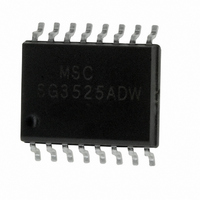
SG3525ADW Microsemi Analog Mixed Signal Group, SG3525ADW Datasheet - Page 3

SG3525ADW
Manufacturer Part Number
SG3525ADW
Description
IC PWM POWER SUPPLY SW 16SOIC
Manufacturer
Microsemi Analog Mixed Signal Group
Datasheet
1.SG3525AN.pdf
(7 pages)
Specifications of SG3525ADW
Pwm Type
Voltage Mode
Number Of Outputs
2
Frequency - Max
350kHz
Duty Cycle
49%
Voltage - Supply
8 V ~ 35 V
Buck
Yes
Boost
No
Flyback
No
Inverting
No
Doubler
No
Divider
No
Cuk
No
Isolated
No
Operating Temperature
0°C ~ 70°C
Package / Case
16-SOIC
Frequency-max
350kHz
Lead Free Status / RoHS Status
Lead free / RoHS Compliant
Available stocks
Company
Part Number
Manufacturer
Quantity
Price
Part Number:
SG3525ADW
Manufacturer:
MSC
Quantity:
20 000
Company:
Part Number:
SG3525ADW(IP3525ADW)
Manufacturer:
SEMELAB
Quantity:
4 599
Part Number:
SG3525ADWR2G
Manufacturer:
ON/安森美
Quantity:
20 000
Rev 1.4a
Copyright
ELECTRICAL CHARACTERISTICS
Oscillator Section
Initial Accuracy
Voltage Stability
Temperature Stability
Minimum Frequency
Maximum Frequency
Current Mirror
Clock Amplitude
Clock Width
Sync Threshold
Sync Input Current
Error Amplifier Section
Input Offset Voltage
Input Bias Current
Input Offset Current
DC Open Loop Gain
Gain-Bandwidth Product
Output Low Level
Output High Level
Common Mode Rejection
Supply Voltage Rejection
P.W.M. Comparator Section (Note 4)
Minimum Duty Cycle
Maximum Duty Cycle
Input Threshold
Input Bias Current
Soft-Start Section
Soft Start Current
Soft Start Voltage
Shutdown Input Current
Output Drivers Section
Output High Level
Output Low Level
Undervoltage Lockout
Collector Leakage
Rise Time
Fall Time
Shutdown Delay
Total Standby Current
Standby Current
1996
Parameter
(Note 4)
(Note 3)
(Note 5)
(Note 4)
(Note 3)
(Note 3)
(Note 3)
(each transistor, V
(V
(Note 3)
CM
= 5.1V)
T
V
MIN
R
R
I
T
Sync Voltage = 3.5V
R
A
V
V
V
V
Zero Duty Cycle
Maximum Duty Cycle
V
V
V
I
I
I
I
V
V
C
C
V
V
RT
SOURCE
SOURCE
SINK
SINK
J
J
IN
V
CM
IN
COMP
COMP
SHUTDOWN
SHUTDOWN
SHUTDOWN
COMP
C
SD
IN
T
T
L
L
L
= 25 C
= 25 C
= 150K , C
= 2K , C
= 2mA
= 0dB, T
= 1nF, T
= 1nF, T
= 35V
(continued)
= 8V to 35V
= 8V to 35V
= 35V
= 3V, C
10M
= 1.5V to 5.2V
= 20mA
= 100mA
C
= 20V)
= 0.6V
= 3.6V
and V
T
= 20mA
= 100mA
J
= 0V
= 2V
= 2.5V
MAX
T
J
J
S
J
SS
T
J
= 25 C
= 25 C
= 25 C
= 0, T
= 1nF
= 25 C
Test Conditions
= High
T
= 0.1 F
J
= 25 C
3
SG1525A/2525A
SG1527A/2527A
Min. Typ. Max. Min. Typ. Max.
37.6
350
1.7
3.0
0.3
1.2
3.8
0.6
60
60
50
45
25
18
17
1
6
±0.3
100
2.0
3.5
0.5
2.0
1.0
0.5
0.2
5.6
0.9
3.3
.05
0.4
0.4
0.2
1.0
0.2
40
±3
75
75
60
49
50
19
18
50
14
1
2
7
11861 Western Avenue
42.4
150
200
600
300
2.2
1.0
2.8
2.5
0.5
3.6
2.0
0.6
1.0
0.4
2.2
0.5
±1
±6
10
80
20
5
1
0
8
37.6
(714) 898-8121
350
1.7
3.0
0.3
1.2
3.8
0.6
60
60
50
45
25
18
17
1
6
SG3525A
SG3527A
100
2.0
3.5
0.5
2.0
1.0
0.2
5.6
0.9
3.3
.05
0.4
0.4
0.2
1.0
0.2
±1
±3
40
75
75
60
49
50
19
18
50
14
2
1
2
7
Garden Grove, CA 92841
42.4
150
200
600
300
2.2
1.0
2.8
2.5
0.5
3.6
2.0
0.6
1.0
0.4
2.2
0.5
±2
±6
10
10
80
20
FAX: (714) 893-2570
1
0
8
Units
MHz
KHz
KHz
mA
mA
mV
mA
mA
Hz
dB
dB
dB
ns
ns
%
%
%
%
V
V
V
V
V
V
V
V
V
V
V
V
A
A
A
A
A
s
s


