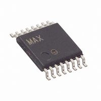
MAX15005BAUE+ Maxim Integrated Products, MAX15005BAUE+ Datasheet - Page 5

MAX15005BAUE+
Manufacturer Part Number
MAX15005BAUE+
Description
IC PWR SUPPLY CNTRLR 16-TSSOP
Manufacturer
Maxim Integrated Products
Datasheet
1.MAX15005BAUE.pdf
(27 pages)
Specifications of MAX15005BAUE+
Pwm Type
Current Mode
Number Of Outputs
1
Frequency - Max
1MHz
Duty Cycle
81.5%
Voltage - Supply
4.5 V ~ 40 V
Buck
No
Boost
Yes
Flyback
Yes
Inverting
No
Doubler
No
Divider
Yes
Cuk
No
Isolated
Yes
Operating Temperature
-40°C ~ 125°C
Package / Case
16-TSSOP
Frequency-max
1MHz
Duty Cycle (max)
80 % (Typ)
Output Voltage
1.23 V to 100 V
Output Current
1000 mA
Mounting Style
SMD/SMT
Switching Frequency
15 KHz to 500 KHz
Maximum Operating Temperature
+ 125 C
Minimum Operating Temperature
- 40 C
Synchronous Pin
Yes
Topology
Boost or Flyback or Forward
Lead Free Status / RoHS Status
Lead free / RoHS Compliant
ELECTRICAL CHARACTERISTICS (continued)
(V
560pF, V
noted. Typical values are at T
Note 1: 100% production tested at +125°C. Limits over the temperature range are guaranteed by design.
Note 2: Guaranteed by design; not production tested.
Note 3: For the MAX15005A/B, D
Note 4: The external SYNC pulse triggers the discharge of the oscillator ramp. See Figure 2. During external SYNC, D
Note 5: The parameter is measured at the trip point of latch, with 0 ≤ V
Note 6: Slope compensation = (2.5 x 10
OUTPUT DRIVER
Driver Output Impedance
Driver Peak Output Current
OVERVOLTAGE COMPARATOR
Overvoltage Comparator Input
Threshold
Overvoltage Comparator
Hysteresis
Overvoltage Comparator Delay
OVI Input Current
THERMAL SHUTDOWN
Shutdown Temperature
Thermal Hysteresis
IN
Flyback/Boost/SEPIC Power-Supply Controllers
= 14V, C
Synchronization section.
the MAX15004A/B; for the MAX15005A/B, there is a shift in D
External Synchronization section).
SYNC
PARAMETER
IN
= V
= 0.1μF, C
OVI
_______________________________________________________________________________________
= V
FB
VCC
= V
A
= +25°C. All voltages are referenced to PGND, unless otherwise noted.) (Note 1) (Figure 5)
CS
= 0.1μF // 1μF, C
MAX
= 0V, COMP = unconnected, OUT = unconnected. T
I
SYMBOL
V
depends upon the value of RT. See Figure 3 and the Oscillator Frequency/External
OUT-PEAK
R
R
V
OV-HYST
T
TD
T
-9
OUT-N
OUT-P
OV-TH
SHDN
I
HYST
OVI
)/C
OVI
SLOPE
REG5
4.5V to 40V Input Automotive
V
I
V
I
C
C
V
From OVI rising above 1.228V to OUT
falling, with 50mV overdrive
V
Temperature rising
mV/μs. See the Applications Information section.
OUT
OUT
CC
CC
OVI
OVI
OUT
OUT
= 1μF, V
= 8V (applied externally),
= 8V (applied externally),
= 100mA (sinking)
= 100mA (sourcing)
rising
= 0 to 5V
= 10nF, sinking
= 10nF, sourcing
ON/OFF
CONDITIONS
MAX
CS
= 5V, C
≤ 0.3V, and FB = COMP.
with f
SYNC
SS
= 0.01μF, C
/f
OSC
A
ratio (see the Oscillator Frequency/
= T
J
= -40°C to +125°C, unless otherwise
SLOPE
MIN
1.20
-0.5
= 100pF, RT = 13.7kΩ, CT =
1.228
1000
TYP
750
125
160
1.7
1.6
15
3
MAX
+0.5
1.26
3.5
5
MAX
= 50% for
UNITS
mA
mV
μA
μs
o
o
Ω
V
C
C
5


