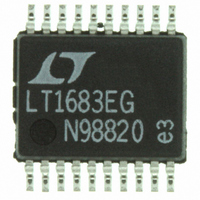
LTC1922EG-1 Linear Technology, LTC1922EG-1 Datasheet - Page 22

LTC1922EG-1
Manufacturer Part Number
LTC1922EG-1
Description
IC CTRLR PWM SYNC 20SSOP
Manufacturer
Linear Technology
Datasheet
1.LTC1922EG-1PBF.pdf
(24 pages)
Specifications of LTC1922EG-1
Pwm Type
Voltage/Current Mode
Number Of Outputs
1
Frequency - Max
1MHz
Duty Cycle
99%
Buck
No
Boost
No
Flyback
No
Inverting
No
Doubler
No
Divider
No
Cuk
No
Isolated
Yes
Operating Temperature
-40°C ~ 85°C
Package / Case
20-SSOP
Frequency-max
1MHz
Lead Free Status / RoHS Status
Contains lead / RoHS non-compliant
Voltage - Supply
-
Available stocks
Company
Part Number
Manufacturer
Quantity
Price
Company:
Part Number:
LTC1922EG-1
Manufacturer:
IBM
Quantity:
942
Part Number:
LTC1922EG-1
Manufacturer:
LT
Quantity:
20 000
OPERATIO
LTC1922-1
the start of a new power cycle. A noninverting MOSFET
driver such as the LTC1693-1 (Figure 14) is used so that
a single signal transformer with secondary center tap can
be employed to translate the drive signals from the pri-
mary to the secondary side. In the event of overcurrent
shutdown, or UVLO condition, both synchronous rectifi-
cation MOSFETs are driven on in order to protect the load
circuitry.
Full-Bridge Gate Drive
The full-bridge converter requires high current MOSFET
gate driver circuitry for two ground referenced switches
and two high side referred switches. Providing drive to the
ground referenced switches is not too difficult as long as
the traces from the gate driver chip or buffer to the gate and
source leads are short and direct. Drive requirements are
22
U
LTC1922-1
LTC1922-1
OUTA
OUTC
OUTE
OUTF
OR
0.1 F
Figure 15. High Side Gate Driver Circuitry
TRANSFORMER
Figure 14. Isolated Drive Circuitry
SIGNAL
1:2
0.1 F
2k
REGULATED
BIAS
BAT
54
further eased since all of the switches turn on with zero
VDS, eliminating the “Miller” effect. Low turn-off resis-
tance is critical, however, in order to prevent excessive
turn-off losses resulting from the same Miller effects that
were not an issue for turn on. The LTC1922-1 does not
require the propagation delays of the high and low side
drive circuits to be precisely matched as the DirectSense
ZVS circuitry will adapt accordingly, unlike previous solu-
tions. As a result, LTC1922-1 can drive a simple NPN-PNP
buffer or a gate driver chip like the LTC1693-1 to provide
the low side gate drive. Providing drive to the high side
presents additional challenges since the MOSFET gate
must be driven above the input supply. A simple circuit
(Figure 15) using a single LTC1693-1, an inexpensive
signal transformer, and a few discrete components pro-
vides both high side gate drives (A and C) reliably.
IN
LTC1693-1
GND
1/2
V
CC
OUT
IN1
GND1
GND2
IN2
LTC1693-1
OUT1
OUT2
2 F
CER
V
IN
POWER
MOSFET
BRIDGE
LEG
1922 F14
1922 F15


