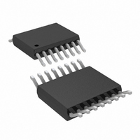
LT3574IMS#PBF Linear Technology, LT3574IMS#PBF Datasheet - Page 17

LT3574IMS#PBF
Manufacturer Part Number
LT3574IMS#PBF
Description
IC PWM FLYBCK ISO CM 16MSOP
Manufacturer
Linear Technology
Type
Flyback, Isolated, PWM - Current Moder
Datasheet
1.LT3574EMSPBF.pdf
(24 pages)
Specifications of LT3574IMS#PBF
Internal Switch(s)
Yes
Synchronous Rectifier
No
Number Of Outputs
1
Voltage - Output
Adj to 60V
Current - Output
650mA
Frequency - Switching
40kHz ~ 1MHz
Voltage - Input
3 ~ 40 V
Operating Temperature
-40°C ~ 125°C
Mounting Type
*
Package / Case
16-MSOP
Voltage - Supply
3 V ~ 40 V
Frequency-max
1MHz
Duty Cycle
52%
Pwm Type
Current Mode
Buck
No
Boost
No
Flyback
Yes
Inverting
No
Doubler
No
Divider
No
Cuk
No
Isolated
Yes
Lead Free Status / RoHS Status
Lead free / RoHS Compliant
Available stocks
Company
Part Number
Manufacturer
Quantity
Price
applications inForMation
During switch turn-off, the energy stored in the leakage
inductance is transferred to the snubber capacitor, and
eventually dissipated in the snubber resistor.
The snubber resistor affects the spike amplitude VC and
duration t
t
to the output voltage sensing.
The previous steps finish the flyback power stage
design.
5. Select the feedback resistor for proper output
Using the resistor Tables 1-4, select the feedback resis-
tor R
R
voltage. R
SP
TC
voltage.
2
1
is about 150ns. Prolonged t
resistor for temperature compensation of the output
FB
L I
S PK SW
, and program the output voltage to 5V. Adjust the
Figure 9. RCD Snubber in a Flyback Converter
2
SP
REF
, the snubber resistor is adjusted such that
f
is selected as 6.04k.
=
C
V V
C
R
(
D
C
L
S
−
R
N V
•
SP
•
OUT
may cause distortion
•
)
3574 F09
A small capacitor in parallel with R
during the voltage spike, however, the capacitor should
limit to 10pF . A large capacitor causes distortion on volt-
age sensing.
6. Optimize the compensation network to improve the
The transient performance is optimized by adjusting the
compensation network. For best ripple performance, select
a compensation capacitor not less than 1nF , and select a
compensation resistor not greater than 50k.
7. Current limit resistor, soft-start capacitor and UVLO
Use the current limit resistor R
limit if a compact transformer design is required. Soft-start
capacitor helps during the start-up of the flyback converter.
Select the UVLO resistor divider for intended input opera-
tion range. These equations are aforementioned.
transient performance.
resistor divider
Figure 10. Typical Switch Node Waveform
V
V
IN
C
t
SP
NV
OUT
LIM
REF
to lower the current
filters out the noise
LT3574
3574 F10
3574f


