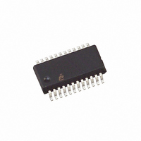
ISL6440IAZ Intersil, ISL6440IAZ Datasheet - Page 4

ISL6440IAZ
Manufacturer Part Number
ISL6440IAZ
Description
IC CTRLR PWM DUAL 300MHZ 24QSOP
Manufacturer
Intersil
Datasheet
1.ISL6440IAZ-T.pdf
(15 pages)
Specifications of ISL6440IAZ
Pwm Type
Current Mode
Number Of Outputs
2
Frequency - Max
340kHz
Duty Cycle
93%
Voltage - Supply
4.5 V ~ 24 V
Buck
Yes
Boost
No
Flyback
No
Inverting
No
Doubler
No
Divider
No
Cuk
No
Isolated
No
Operating Temperature
-40°C ~ 85°C
Package / Case
24-QSOP
Frequency-max
340kHz
Lead Free Status / RoHS Status
Lead free / RoHS Compliant
Available stocks
Company
Part Number
Manufacturer
Quantity
Price
Company:
Part Number:
ISL6440IAZ
Manufacturer:
Intersil
Quantity:
800
Part Number:
ISL6440IAZ
Manufacturer:
INTERSIL
Quantity:
20 000
Part Number:
ISL6440IAZ-T
Manufacturer:
INTERSIL
Quantity:
20 000
Company:
Part Number:
ISL6440IAZ-TK
Manufacturer:
Intersil
Quantity:
1 550
Part Number:
ISL6440IAZ-TK
Manufacturer:
INTERSIL
Quantity:
20 000
Absolute Maximum Ratings
Supply Voltage (VCC_5V Pin) . . . . . . . . . . . . . . . . . . . . -0.3V to +7V
Input Voltage (VIN Pin) . . . . . . . . . . . . . . . . . . . . . . . . . . . . . . .+27V
BOOT1, 2 and UGATE1, 2. . . . . . . . . . . . . . . . . . . . . . . . . . . . +35V
PHASE1, 2 and ISEN1, 2 . . . . . . . . . . . . . . . . . . . . . . . . . . . . +27V
BOOT1, 2 with Respect to PHASE1, 2 . . . . . . . . . . . . . . . . . . +6.5V
UGATE1, 2. . . . . . . . . . . . (PHASE1, 2 - 0.3V) to (BOOT1, 2 +0.3V)
CAUTION: Stresses above those listed in “Absolute Maximum Ratings” may cause permanent damage to the device. This is a stress only rating and operation of the
device at these or any other conditions above those indicated in the operational sections of this specification is not implied.
NOTE:
Electrical Specifications
VIN SUPPLY
Input Voltage Range
VCC_5V SUPPLY (Note 3)
Input Voltage
Output Voltage
Maximum Output Current
SUPPLY CURRENT
Shutdown Current (Note 4)
Operating Current (Note 5)
REFERENCE SECTION
Nominal Reference Voltage
Reference Voltage Tolerance
POWER-ON RESET
Rising VCC_5V Threshold
Falling VCC_5V Threshold
OSCILLATOR
Total Frequency Variation
Peak-to-Peak Sawtooth Amplitude (Note 6)
Ramp Offset (Note 7)
SHUTDOWN1/SHUTDOWN2
HIGH Level (Converter Enabled)
LOW Level (Converter Disabled)
PWM CONVERTERS
Output Voltage
FB Pin Bias Current
Maximum Duty Cycle
Minimum Duty Cycle
1. θ
JA
is measured with the component mounted on a high effective thermal conductivity test board in free air. See Tech Brief TB379 for details.
PARAMETER
4
Recommended operating conditions unless otherwise noted. Refer to Block Diagram and Typical Application
Schematic. V
Typical values are at T
IN
= 5.6V to 24V, or VCC5 = 5V ±10%, T
V
V
SD1 = SD2 = GND
V
V
Internal Pull-up (3µA)
Cout = 1000pF, T
IN
IN
IN
IN
A
> 5.6V, I
= 12V
= 12V
= 5V
= 25°C
TEST CONDITIONS
ISL6440
L
= 20mA
A
= 25°C
Thermal Information
Thermal Resistance (Typical)
Maximum Junction Temperature (Plastic Package) . -55°C to 150°C
Maximum Storage Temperature Range . . . . . . . . . . . -65°C to 150°C
Maximum Lead Temperature (Soldering 10s) . . . . . . . . . . . . . 300°C
Temperature Range . . . . . . . . . . . . . . . . . . . . . . . . . . . -40°C to 85°C
24 Lead QSOP (Note 1). . . . . . . . . . . . . . . . . . . . . .
A
= -40°C to 85°C (Note 3),
MIN
4.25
3.95
-1.0
260
5.6
4.5
4.5
2.0
60
93
-
-
-
-
-
-
-
-
-
-
0.667
TYP
4.45
300
5.0
5.0
2.0
0.8
4.2
1.6
1.0
0.8
12
50
4
-
-
-
-
-
-
MAX
375
340
150
5.6
5.5
4.0
1.0
4.5
4.4
0.8
24
-
-
-
-
-
-
-
-
-
October 4, 2005
θ
JA
UNITS
kHz
mA
mA
µA
nA
%
%
%
FN9040.2
V
V
V
V
V
V
V
V
V
V
V
V
(°C/W)
85


