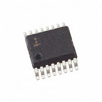
ISL6224CA Intersil, ISL6224CA Datasheet - Page 6

ISL6224CA
Manufacturer Part Number
ISL6224CA
Description
IC CONTROLLER PWM SINGLE 16-SSOP
Manufacturer
Intersil
Datasheet
1.ISL6224CAZ.pdf
(13 pages)
Specifications of ISL6224CA
Pwm Type
Current Mode
Number Of Outputs
1
Frequency - Max
690kHz
Duty Cycle
94%
Voltage - Supply
4 V ~ 24 V
Buck
Yes
Boost
No
Flyback
No
Inverting
No
Doubler
No
Divider
No
Cuk
No
Isolated
No
Operating Temperature
-10°C ~ 85°C
Package / Case
16-QSOP
Frequency-max
690kHz
Lead Free Status / RoHS Status
Contains lead / RoHS non-compliant
Available stocks
Company
Part Number
Manufacturer
Quantity
Price
Part Number:
ISL6224CA
Manufacturer:
INTERSIL
Quantity:
20 000
Part Number:
ISL6224CAZ
Manufacturer:
INTERSIL
Quantity:
20 000
Company:
Part Number:
ISL6224CAZ-T
Manufacturer:
INTERSIL
Quantity:
6 387
grounded. Table 1. shows the configuration for different
modes of operation. Figure 1 below shows plots of the ramp
speed compensation.
The synchronous converter light-load efficiency is enhanced
by a hysteretic mode of operation which is automatically
engaged at light loads when the inductor current becomes
discontinuous. As the filter inductor resumes continuous
current, the PWM mode of operation is automatically
restored.
The ISL6224 control IC employs an average current mode
control scheme with input voltage feedforward ramp
programming for better rejection of input voltage variations.
Current Sensing and Current Limit Protection
The PWM converter uses the lower MOSFET on-state
resistance, r
technique eliminates the need for a current sense resistor
and the associated power losses. If more accurate current
protection is desired, current sense resistors may be used in
series with the lower MOSFET’s source.
A current proportional signal is used to provide average
current mode control and overcurrent protection. The gain in
the current sense circuit is set by the resistor connected from
ISEN (pin 12) to the PHASE node of the buck converter. The
value of this resistor can be estimated by the following
expression:
where Iomax is the maximum inductor current. The value of
R
operating temperature.
An overcurrent protection threshold is set by an external
resistor connected from OCSET (pin 4) to ground. The value
One-stage 300kHz
Two-stage 300kHz
Two-stage 600kHz
Risen
ISEN
TABLE 1. CONFIGURATION FOR MODES OF OPERATION
OPERATION
FIGURE 1. RAMP SPEED COMPENSATION Vo = 2.5V
should be specified for the expected maximum
=
300kHz CLOCK
600kHz CLOCK
Iomax Rdson
------------------------------------------ - 100
Vo/4
DS(ON)
75µA
•
Vin
--------- -
, as the current-sensing element. This
2
PIN 1 CONNECTION
-- -
T
t
–
150K-GND
GND
Vin
6
Vo/8
Vin
--------- - t
4
-- -
T
PIN 1 POTENTIAL
1V < V1 < 2V
V1 < 0.5V
V1 > 4V
Vin
--------- -
8
-- -
T
t
ISL6224
of this resistor can be obtained from the following
expression:
where Ioc is the value of overcurrent. The resulting current
out of the ISEN pin through R
feedback and current limit protection. This is compared with
an internal current limit threshold. When a sampled value of
the output current is determined to be above the current limit
threshold, the PWM drive is terminated and a counter is
initiated. This limits the inductor current build-up and
essentially switches the converter into current-limit mode. If
an overcurrent is detected between 26ms to 53ms later, an
overcurrent shutdown is initiated. If during the 26ms to 53ms
period, an overcurrent is not detected, the counter is reset
and sampling continues as normal.
This current limit scheme has proven to be very robust in
applications like portable computers where fast inductor
current build-up is common due to a large difference
between input and output voltages and a low value of the
inductor.
Light-Load (Hysteretic) Operation
In the light-load (hysteretic) mode the output voltage is
regulated by the hysteretic comparator which regulates the
output voltage by maintaining the output voltage ripple as
shown in Figure 2. In hysteretic mode, the inductor current
flows only when the output voltage reaches the lower limit of
the hysteretic comparator and turns off at the upper limit.
Hysteretic mode saves converter energy at light loads by
supplying energy only at the time when the output voltage
requires it. This mode conserves energy by reducing the
power dissipation associated with continuous switching.
During the time between inductor current pulses, both the
upper and lower MOSFETs are turned off. This is referred to
as ‘diode emulation mode’ because the lower MOSFET
performs the function of a diode. This diode emulation mode
prevents the output capacitor from discharging through the
lower MOSFET when the upper MOSFET is not conducting.
NOTE: the PWM only operation can intentionally be forced by tying
pin 16, FCCM, to VCC.
Rocset
=
---------------------------------
Ioc Rdson
11 Risen
•
•
ISEN
, is used for current
June 8, 2006
FN9042.8


