LP2996LQ/NOPB National Semiconductor, LP2996LQ/NOPB Datasheet - Page 15
LP2996LQ/NOPB
Manufacturer Part Number
LP2996LQ/NOPB
Description
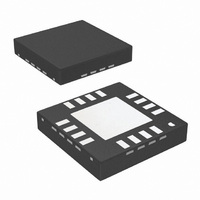
IC DDR TERMINATION REG 16LLP
Manufacturer
National Semiconductor
Datasheet
1.LP2996MNOPB.pdf
(18 pages)
Specifications of LP2996LQ/NOPB
Applications
Converter, DDR
Voltage - Input
2.2 ~ 5.5 V
Number Of Outputs
1
Operating Temperature
0°C ~ 125°C
Mounting Type
Surface Mount
Package / Case
16-LLP
Polarity
Positive
Input Voltage Max
5.5 V
Output Voltage
1.159 V, 1.259 V, 1.359 V
Output Type
Fixed
Output Current
1.5 A
Maximum Operating Temperature
+ 125 C
Mounting Style
SMD/SMT
Minimum Operating Temperature
0 C
Reference Voltage
1.358 V
Primary Input Voltage
2.5V
No. Of Outputs
1
No. Of Pins
16
Operating Temperature Range
0°C To +125°C
Msl
MSL 3 - 168 Hours
Input Voltage Primary Max
5V
Rohs Compliant
Yes
For Use With
LP2996LQEVAL - BOARD EVALUATION LP2996LQ
Lead Free Status / RoHS Status
Lead free / RoHS Compliant
Voltage - Output
-
Lead Free Status / Rohs Status
Details
Other names
LP2996LQ
LP2996LQTR
LP2996LQTR
Available stocks
Company
Part Number
Manufacturer
Quantity
Price
Company:

Part Number:
LP2996LQ/NOPB
Manufacturer:
National Semiconductor
Quantity:
1 785


PCB Layout Considerations
1.
2.
3.
4.
The input capacitor for the power rail should be placed
as close as possible to the PVIN pin.
V
at the point where regulation is required. For
motherboard applications an ideal location would be at
the center of the termination bus.
V
either the DIMM or the Chipset. This provides the most
accurate point for creating the reference voltage.
For improved thermal performance excessive top side
copper should be used to dissipate heat from the
SENSE
DDQ
can be connected remotely to the V
should be connected to the V
TT
termination bus
DDQ
rail input at
15
5.
6.
package. Numerous vias from the ground connection to
the internal ground plane will help. Additionally these can
be located underneath the package if manufacturing
standards permit.
Care should be taken when routing the V
avoid noise pickup from switching I/O signals. A 0.1uF
ceramic capacitor located close to the
used to filter any unwanted high frequency signal. This
can be an issue especially if long
V
ceramic capacitor for improved performance. This
capacitor should be located as close as possible to the
V
REF
REF
should be bypassed with a 0.01 µF or 0.1 µF
pin.
SENSE
SENSE
traces are used.
SENSE
www.national.com
can also be
trace to
Related parts for LP2996LQ/NOPB
Image
Part Number
Description
Manufacturer
Datasheet
Request
R

Part Number:
Description:
DDR Termination Regulator
Manufacturer:
National Semiconductor
Datasheet:
Part Number:
Description:
National Semiconductor [8-Bit D/A Converter]
Manufacturer:
National Semiconductor
Datasheet:
Part Number:
Description:
National Semiconductor [Media Coprocessor]
Manufacturer:
National Semiconductor
Datasheet:
Part Number:
Description:
Digitally Controlled Tone and Volume Circuit with Stereo Audio Power Amplifier, Microphone Preamp Stage and National 3D Sound
Manufacturer:
National Semiconductor
Datasheet:
Part Number:
Description:
Digitally Controlled Tone and Volume Circuit with Stereo Audio Power Amplifier, Microphone Preamp Stage and National 3D Sound
Manufacturer:
National Semiconductor
Datasheet:
Part Number:
Description:
AC97 Rev 2 Codec with Sample Rate Conversion and National 3D Sound
Manufacturer:
National Semiconductor
Part Number:
Description:
Manufacturer:
National Semiconductor
Datasheet:
Part Number:
Description:
Manufacturer:
National Semiconductor
Datasheet:
Part Number:
Description:
General Purpose, Low Voltage, Low Power, Rail-to-Rail Output Operational Amplifiers
Manufacturer:
National Semiconductor
Datasheet:
Part Number:
Description:
8-bit 20 MSPS flash A/D converter.
Manufacturer:
National Semiconductor
Datasheet:
Part Number:
Description:
Low Noise Quad Operational Amplifier
Manufacturer:
National Semiconductor
Datasheet:
Part Number:
Description:
Quad Differential Line Receivers
Manufacturer:
National Semiconductor
Datasheet:
Part Number:
Description:
Quad High Speed Trapezoidal? Bus Transceiver
Manufacturer:
National Semiconductor
Datasheet:
Part Number:
Description:
Dual Line Receiver
Manufacturer:
National Semiconductor
Datasheet: