ISL6423BERZ-T Intersil, ISL6423BERZ-T Datasheet - Page 8
ISL6423BERZ-T
Manufacturer Part Number
ISL6423BERZ-T
Description
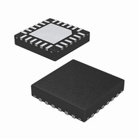
IC VREG SGL LNB W/I2C 24-QFN
Manufacturer
Intersil
Datasheet
1.ISL6423BERZ.pdf
(16 pages)
Specifications of ISL6423BERZ-T
Applications
Converter, Satellite Set-Top Box Designs
Voltage - Input
8 ~ 14 V
Number Of Outputs
1
Voltage - Output
13.3 ~ 18.3 V, 14.3 ~ 19.3 V
Operating Temperature
-20°C ~ 85°C
Mounting Type
Surface Mount
Package / Case
24-VQFN
Lead Free Status / RoHS Status
Lead free / RoHS Compliant
Available stocks
Company
Part Number
Manufacturer
Quantity
Price

Part Number:
ISL6423BERZ-T
Manufacturer:
INTERSIL
Quantity:
20 000
Part Number:
ISL6423BERZ-TR5434
Manufacturer:
INTERSIL
Quantity:
20 000


Typical Performance Curves
Functional Pin Description
CPVOUT, CPSWIN
ADDR0 & ADDR1
TDIN, TDOUT
0.80
0.70
0.60
0.50
0.40
0.30
0.20
0.10
0.00
FIGURE 2. OUTPUT CURRENT DERATING (EPTSSOP)
CPSWOUT
SELVTOP
SYMBOL
BYPASS
PGND
SGND
EXTM
TCAP
GATE
VSW
0
SDA
VCC
SCL
TXT
FLT
CS
VO
20
Bidirectional data from/to I
Clock from I
Input of the linear post-regulator.
Dedicated ground for the output gate driver of respective PWM.
Current sense input; connect the sense resistor Rsc at this pin for desired peak overcurrent value for the boost FET. The
set peak limit is effective in the static mode current limit only i.e., DCL = HIGH.
Small signal ground for the IC.
Capacitor for setting rise and fall time of the output voltage. Typical value is 0.1µF.
Bypass capacitor for internal 5V.
TXT is the Tone Transmit signal input used to change the Tone Decoder Threshold from TXT = 0, 200mV max during
Receive to TXT = 1, 400mV min during Transmit.
Main power supply to the chip.
This output drives the boost FET gate. The output is held low when V
Output voltage for the LNB is available at VO pin.
Logic combination at the ADDR0 & 1 can select four different chip select addresses.
This pin can be used in two ways:
1) As an input for externally modulated Diseqc tone signal which is transferred to the symmetrically onto V
2) Alternatively apply a Diseqc modulation envelope which modulates an internal tone and then transfers it symmetrically
onto V
This is an Open Drain output from the controller. When the FLT goes low it indicates that an Over Temperature, Over load
fault, UVLO, or an I
cause of the error. A high on the FLT indicates that the device is functioning normally.
A 47n charge pump decoupling capacitor is to be connected to CPVOUT. Connect a 1.5n capacitor between CPSWIN and
CPSWOUT
When this pin is low the V
When this pin is high the 18V, 19V range selected by the I
be set low for the SELVTOP pins to be active. Setting VSPEN high disables this pins and voltage selection will be done
using the I
TDIN is the tone decoder input and TDOUT is the tone detector output. TDOUT is an open drain output
TEMPERATURE (°C)
OUT
8
2
C bits VBOT and VTOP only.
2
40
C bus.
2
C reset condition has occurred. The processor should then look at the I
60
OUT
2
C bus.
I
OUT
is in the 13V, 14V range selected by the I
_max
80
FUNCTION
2
C bit VTOP. The Voltage select pin enable VSPEN I
0.80
0.70
0.60
0.50
0.40
0.30
0.20
0.10
0.00
FIGURE 3. OUTPUT CURRENT DERATING (4x4 QFN)
0
CC
2
is below the UVLO threshold.
C bit VBOT.
20
TEMPERATURE (°C)
40
2
C register to get the actual
60
OUT
I
OUT
2
C bit must
April 10, 2007
_max
FN6412.1
80
Related parts for ISL6423BERZ-T
Image
Part Number
Description
Manufacturer
Datasheet
Request
R

Part Number:
Description:
Single Output LNB Supply and Control Voltage Regulator
Manufacturer:
Intersil Corporation
Datasheet:
Part Number:
Description:
Single Output Lnb Supply And Control Voltage Regulator With I2c Interface For Advanced Satellite Set-top Box Designs, Diseqc 2.0 Compatible
Manufacturer:
Intersil Corporation
Datasheet:
Part Number:
Description:
Intersil Corporation [CMOS Serial Controller Interface]
Manufacturer:
Intersil Corporation
Datasheet:
Part Number:
Description:
Manufacturer:
Intersil Corporation
Datasheet:
Part Number:
Description:
357-036-542-201 CARDEDGE 36POS DL .156 BLK LOPRO
Manufacturer:
Intersil Corporation
Datasheet:
Part Number:
Description:
1024-Word x 4-Bit LSI Static RAM
Manufacturer:
Intersil Corporation
Datasheet:
Part Number:
Description:
General Purpose NPN Transistor Arrays FN341.4
Manufacturer:
Intersil Corporation
Datasheet:
Part Number:
Description:
CMOS 16-Bit Microprocessor
Manufacturer:
Intersil Corporation
Datasheet:
Part Number:
Description:
Manufacturer:
Intersil Corporation
Datasheet:
Part Number:
Description:
Manufacturer:
Intersil Corporation
Datasheet:
Part Number:
Description:
Manufacturer:
Intersil Corporation
Datasheet:
Part Number:
Description:
Manufacturer:
Intersil Corporation
Datasheet:
Part Number:
Description:
CMOS 6-Bit Latch and Decoder Memory Interfaces
Manufacturer:
Intersil Corporation
Datasheet:
Part Number:
Description:
CA3046General Purpose NPN Transistor Arrays
Manufacturer:
Intersil Corporation
Datasheet:
Part Number:
Description:
Manufacturer:
Intersil Corporation
Datasheet: