ISL8101IRZ-T Intersil, ISL8101IRZ-T Datasheet
ISL8101IRZ-T
Specifications of ISL8101IRZ-T


Related parts for ISL8101IRZ-T

ISL8101IRZ-T Summary of contents
Page 1
... PART TEMP. (Note) MARKING (°C) ISL8101CRZ* 81 01CRZ 0 to +70 (Note) ISL8101IRZ* 81 01IRZ - 4x4 QFN (Note) ISL8101EVAL1 Evaluation Platform Please refer to TB347 for details on reel *Add “-T” suffix for tape and reel. specifications. These Intersil Pb-free plastic packaged products employ special ...
Page 2
Block Diagram OVP WHILE DISABLED 1.65V/1.95V + - OVP + 200mV - COMP VID0 VID1 VID2 TTL D/A CONVERTER VID3 (VID DAC) EA VID4 DACSEL/VID5 + VRM10 - FB OFFSET SOURCE GND OFS SSEND ENLL VCC POWER-ON RESET (POR) OSCILLATOR ...
Page 3
Simplified Power System Diagram +5V IN 5-6 VID Typical Application +12V IN + DACSEL/VID12 VID4 VID3 VID2 VID1 VID0 VRM10 R ISEN ISEN SSEND R’ OFS ISL8101 ENLL OFS R OFS COMP ...
Page 4
... V + 0.3V Maximum Storage Temperature Range . . . . . . . . . .-65°C to +150°C BOOT - 0. 0.3V Pb-Free Reflow Profile .see link below GND CC + 0.3V http://www.intersil.com/pbfree/Pb-FreeReflow.asp 0°C to +85°C, Unless Otherwise Specified. Parameters with MIN and/or MAX CC J TEST CONDITIONS I ; ENLL = high VCC VCC Rising ...
Page 5
Electrical Specifications Test Conditions: V limits are 100% tested at +25°C, unless otherwise specified. Temperature limits established by characterization and are not production tested. (Continued) PARAMETER OVERCURRENT PROTECTION Overcurrent Trip Level PROTECTION Overvoltage Threshold while IC Disabled Overvoltage Threshold Overvoltage ...
Page 6
GND pin. LGATE drive is referenced to the PGND pin. VID0-4 (Pins 2, 1, 24-22) Voltage identification inputs from microprocessor. These pins respond to TTL logic thresholds. The ISL8101 decodes the VID inputs to establish the output ...
Page 7
Operation The ISL8101 employs simple voltage-mode control. Figure 1 shows a simplified diagram of the voltage regulation and current balance loops. Voltage feedback is used to precisely regulate the output voltage, while current feedback tightly controls the individual channel currents, ...
Page 8
INTERLEAVING The switching of each channel in a ISL8101-based converter is timed to be symmetrically out of phase with the other channel result, the two-phase converter has a combined ripple frequency twice the frequency of one of its ...
Page 9
... In order to fully realize the thermal advantage important that each channel in a multiphase converter be controlled to deliver about the same current at any load level. Intersil multiphase controllers ensure current balance by comparing each channel’s current to the average current delivered by all channels and making appropriate adjustments to each channel’ ...
Page 10
TABLE 1. AMD HAMMER VOLTAGE IDENTIFICATION CODES (Continued) VID4 VID3 VID2 VID1 ...
Page 11
TABLE 3. VRM10 VOLTAGE IDENTIFICATION CODES (Continued) VID4 VID3 VID2 VID1 VID0 ...
Page 12
OVERVOLTAGE PROTECTION The ISL8101 benefits from a multi-tiered approach to overvoltage protection. A pre-POR mechanism is at work while the chip does not have sufficient bias voltage to initiate an active response situation. Thus, while VCC is ...
Page 13
DAC setting. Should the output be pre-charged to a level exceeding the DAC setting, the output drives are ...
Page 14
... C C ⎠ ⎠ many of the basic skills and techniques referenced below ⋅ ⋅ = 2π addition to this guide, Intersil provides complete reference designs that include schematics, bills of materials, and example board layouts for all common microprocessor applications. 1 ⋅ MOSFETs 1 2 ⋅ -------------------- - (EQ ...
Page 15
MOSFET can be found in Equation 15. ⎛ ⎞ P ⎜ OUT ⎟ ---------------------------------- = – ------------ - LMOS1 DS ON ⎝ ⎠ ...
Page 16
At the beginning of the load transient, the output capacitors supply all of the transient current. The output voltage will initially deviate by an amount approximated by the voltage drop across the ESL. As the load current increases, the voltage ...
Page 17
It is especially important to locate the components associated with the feedback circuit close to their respective controller pins, since they belong to a high- impedance circuit loop, sensitive to EMI pick-up important to ...
Page 18
Component Selection Guidelines Output Capacitor Selection The output capacitor is selected to meet both the dynamic load requirements and the voltage ripple requirements. The load transient a microprocessor impresses is characterized by high slew rate (di/dt) current demands. In general, ...
Page 19
... Accordingly, the reader is cautioned to verify that data sheets are current before placing orders. Information furnished by Intersil is believed to be accurate and reliable. However, no responsibility is assumed by Intersil or its subsidiaries for its use; nor for any infringements of patents or other rights of third parties which may result from its use ...
Page 20
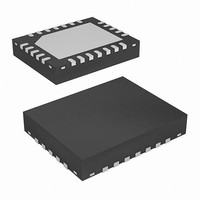
Package Outline Drawing L24.4x4B 24 LEAD QUAD FLAT NO-LEAD PLASTIC PACKAGE Rev 2, 10/06 4.00 PIN 1 INDEX AREA (4X) 0.15 TOP VIEW ( TYP ) ( TYPICAL RECOMMENDED LAND PATTERN 20 ISL8101 ...