ISL6225CAZ-T Intersil, ISL6225CAZ-T Datasheet - Page 8
ISL6225CAZ-T
Manufacturer Part Number
ISL6225CAZ-T
Description
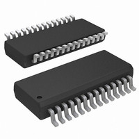
IC CTRLR DDR DRAM, SDRAM 28QSOP
Manufacturer
Intersil
Datasheet
1.ISL6225CAZ.pdf
(19 pages)
Specifications of ISL6225CAZ-T
Applications
Controller, DDR DRAM, SDRAM
Voltage - Input
5 ~ 24 V
Number Of Outputs
2
Voltage - Output
0.9 ~ 5.5 V
Operating Temperature
-10°C ~ 85°C
Mounting Type
Surface Mount
Package / Case
28-QSOP
Lead Free Status / RoHS Status
Lead free / RoHS Compliant
Available stocks
Company
Part Number
Manufacturer
Quantity
Price
Company:

Part Number:
ISL6225CAZ-T
Manufacturer:
INTERSIL
Quantity:
1 608
Part Number:
ISL6225CAZ-T
Manufacturer:
INTERSIL
Quantity:
20 000


Description
Operation
The ISL6225 is a dual channel PWM controller intended for
use in power supplies for graphic chipset, SDRAM, DDR
DRAM or other low voltage power applications in modern
notebook and sub-notebook PCs. The IC integrates two
control circuits for two synchronous buck converters. The
output voltage of each controller can be set in the range of
0.9V to 5.5V by an external resistive divider. Out-of-phase
operation with 180 degree phase shift reduces input current
ripple.
The synchronous buck converters can operate from either
an unregulated DC source such as a notebook battery with a
voltage ranging from 5.0V to 24V, or from a regulated system
rail of 3.3V or 5V. In either mode of operation the controller is
biased from the +5V source.
The controllers operate in the current mode with input
voltage feed-forward for simplified feedback loop
compensation and reduced effect of the input voltage
variation. An integrated feedback loop compensation
dramatically reduces the number of external components.
Depending on the load level, converters can operate either
in a fixed-frequency mode or in a hysteretic mode. Switch-
over to the hysteretic mode operation at light loads improves
the converters' efficiency and prolongs battery run time. The
hysteretic mode of operation can be inhibited independently
for each channel if a variable frequency operation is not
desired.
The ISL6225 has a special means to rearrange its internal
architecture into a complete DDR solution. When DDR input
is set high, the second channel can provide the capability to
track the output voltage of the first channel. The buffered
reference voltage required by DDR memory chips is also
provided.
Initialization
The Power-On Reset (POR) function continually monitors
the bias supply voltage on the V
operation after the input supply voltage exceeds 4.5V.
Should this voltage drop lower than 4.0V, the POR disables
the chip.
Soft-Start
When soft-start is initiated, the voltage on the SOFT pin
starts to ramp gradually due to the 5
the external soft-start capacitor. The output voltage starts to
follow the soft-start voltage.
When the SOFT pin voltage reaches a level of 0.9V, the
output voltage comes into regulation while the soft-start pin
voltage continues to rise. When the SOFT voltage reaches
8
CC
pin and initiates soft-start
µ
A current sourced into
1.5V, the power good (PGOOD), the mode control, and the
fault functions are enabled, as depicted in Figure 3.
This completes the soft-start sequence. Further rise of pin
voltage does not affect the output voltage. During the soft-
start, the converter always operates in continuous
conduction mode independently of the load level or FCCM
pin potential.
The soft-start time (the time from the moment when EN
becomes high to the moment when PGOOD is reported) is
determined by the following equation.
The time it takes the output voltage to come into regulation
can be obtained from the following equation.
Having such a spread between the time when the output
voltage reaches the regulation point and the moment when
PGOOD is reported allows for a fault-safe test mode by
means of an external circuit that clamps the SOFT pin
voltage on the level 0.9V < V
Output Voltage Program
The output voltage of either channel is set by a resistive divider
from the output to ground. The center point of the divider is
connected to VSEN pin as shown in Figure 4. The output
voltage value is determined by the following equation.
Where 0.9V is the value of the internal reference. The VSEN
pin voltage is also used by the controller for the power good
function and to detect Undervoltage and Overvoltage
conditions.
T SOFT
T RISE
V O
=
3
1
2
4
0.9V
--------------------------------------------- -
Ch1 5.0V
Ch3 1.0V
=
=
0.6
1.5V Csoft
----------------------------------
•
(
R2
×
0.9V
R1
PGOOD
5µA
T SOFT
×
EN
+
VOUT
1.5V
R2
FIGURE 3. START UP
)
Ch2 2.0V
Ch4 5.0V
SOFT
SOFT
< 1.5V.
M1.00ms
December 28, 2004
FN9049.7
Related parts for ISL6225CAZ-T
Image
Part Number
Description
Manufacturer
Datasheet
Request
R

Part Number:
Description:
Dual Mobile-friendly Pwm Controller With Ddr Memory Option
Manufacturer:
Intersil Corporation
Datasheet:
Part Number:
Description:
Intersil Corporation [CMOS Serial Controller Interface]
Manufacturer:
Intersil Corporation
Datasheet:
Part Number:
Description:
Manufacturer:
Intersil Corporation
Datasheet:
Part Number:
Description:
357-036-542-201 CARDEDGE 36POS DL .156 BLK LOPRO
Manufacturer:
Intersil Corporation
Datasheet:
Part Number:
Description:
1024-Word x 4-Bit LSI Static RAM
Manufacturer:
Intersil Corporation
Datasheet:
Part Number:
Description:
General Purpose NPN Transistor Arrays FN341.4
Manufacturer:
Intersil Corporation
Datasheet:
Part Number:
Description:
CMOS 16-Bit Microprocessor
Manufacturer:
Intersil Corporation
Datasheet:
Part Number:
Description:
Manufacturer:
Intersil Corporation
Datasheet:
Part Number:
Description:
Manufacturer:
Intersil Corporation
Datasheet:
Part Number:
Description:
Manufacturer:
Intersil Corporation
Datasheet:
Part Number:
Description:
Manufacturer:
Intersil Corporation
Datasheet:
Part Number:
Description:
CMOS 6-Bit Latch and Decoder Memory Interfaces
Manufacturer:
Intersil Corporation
Datasheet:
Part Number:
Description:
CA3046General Purpose NPN Transistor Arrays
Manufacturer:
Intersil Corporation
Datasheet:
Part Number:
Description:
Manufacturer:
Intersil Corporation
Datasheet:
Part Number:
Description:
TR909 DLC/FLC SLIC with Low Power Standby
Manufacturer:
Intersil Corporation
Datasheet: