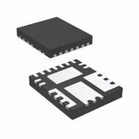
IR3842WMTR1PBF International Rectifier, IR3842WMTR1PBF Datasheet - Page 17

IR3842WMTR1PBF
Manufacturer Part Number
IR3842WMTR1PBF
Description
IC REG SYNC BUCK 4A 15-QFN
Manufacturer
International Rectifier
Series
SupIRBuck™r
Type
Step-Down (Buck)r
Datasheet
1.IR3842WMTR1PBF.pdf
(34 pages)
Specifications of IR3842WMTR1PBF
Internal Switch(s)
Yes
Synchronous Rectifier
Yes
Number Of Outputs
1
Voltage - Output
0.7 ~ 14.4 V
Current - Output
4A
Frequency - Switching
225kHz ~ 1.65MHz
Voltage - Input
1.5 ~ 16 V
Operating Temperature
-40°C ~ 125°C
Mounting Type
Surface Mount
Package / Case
15-PowerVQFN
Power - Output
640mW
Primary Input Voltage
16V
No. Of Outputs
1
Output Voltage
14.4V
Output Current
4A
No. Of Pins
15
Operating Temperature Range
-40°C To +125°C
Output Voltage Adjustable Max, Vout
14.4V
Rohs Compliant
Yes
Part Status
Preferred
Package
PQFN / 5 x 6
Circuit
Single Output
Iout (a)
4
Switch Freq (khz)
250 - 1500
Input Range (v)
1.5 - 16
Output Range (v)
0.7 - 0.9*Vin
Ocp Otp Uvlo Pre-bias Soft Start And
PGOOD + EN + SEQ + OVD
Design Tool
Yes
Server Storage
Yes
Routers Switches
Yes
Base Station Telecom
Yes
Lead Free Status / RoHS Status
Lead free / RoHS Compliant
Other names
IR3842WMTR1PBFTR
Minimum on time Considerations
The minimum ON time is the shortest amount of
time for which the Control FET may be reliably
turned on, and this depends on the internal
timing delays. For the IR3842W, the typical
minimum on-time is specified as 50 ns.
Any design or application using the IR3842W
must ensure operation with a pulse width that is
higher than this minimum on-time and preferably
higher than 100 ns. This is necessary for the
circuit to operate without jitter and pulse-
skipping, which can cause high inductor current
ripple and high output voltage ripple.
In any application that uses the IR3842W, the
following condition must be satisfied:
The minimum output voltage is limited by the
reference voltage and hence V
Therefore, for V
Therefore, at the maximum recommended input
voltage 16V and minimum output voltage, the
converter should be designed at a switching
frequency that does not exceed 440 kHz.
Conversely, for operation at the maximum
recommended operating frequency 1.65 MHz
and minimum output voltage, any voltage above
4.2 V may not be stepped down without pulse-
skipping.
Rev 11.0
∴
∴
V
∴
∴
in
t
V
on
V
t
×
in
on
t
(min)
in
on
F
×
(min)
×
s
out(min)
F
=
=
F
s
≤
≤
V
s
F
D
≤
≤
in
V
t
s
V
≤
on
t
V
out
100
out
×
on
0.7
= 0.7 V,
t
in
V
on
V
(min)
(min)
F
out
×
out
(min)
s
ns
V
F
s
=
7 ×
out(min)
10
6
V/s
= 0.7 V.
Maximum Duty Ratio Considerations
A fixed off-time of 200 ns maximum is specified
for the IR3842W. This provides an upper limit on
the operating duty ratio at any given switching
frequency. It is clear that, higher the switching
frequency, the lower is the maximum duty ratio at
which the IR3842W can operate. To allow a
margin of 50 ns, the maximum operating duty
ratio in any application using the IR3842W
should still accommodate about 250 ns off-time.
Fig 10. shows a plot of the maximum duty ratio
v/s the switching frequency, with 250 ns off-time.
95
90
85
80
75
70
65
60
55
Fig. 10. Maximum duty cycle v/s switching
250
450
frequency.
650
S w itching Frequency (kH z )
M a x Duty Cycle
IR3842WMPbF
850
1050
1250
1450
17
1650


