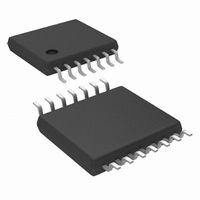
LM2852YMXA-2.5/NOPB National Semiconductor, LM2852YMXA-2.5/NOPB Datasheet - Page 13

LM2852YMXA-2.5/NOPB
Manufacturer Part Number
LM2852YMXA-2.5/NOPB
Description
IC REG SYNC BUCK 2A 2.5V 14TSSOP
Manufacturer
National Semiconductor
Series
PowerWise®, SIMPLE SWITCHER®r
Type
Step-Down (Buck)r
Datasheet
1.LM2852YMXA-3.3NOPB.pdf
(14 pages)
Specifications of LM2852YMXA-2.5/NOPB
Internal Switch(s)
Yes
Synchronous Rectifier
Yes
Number Of Outputs
1
Voltage - Output
2.5V
Current - Output
2A
Frequency - Switching
500kHz
Voltage - Input
2.85 ~ 5.5 V
Operating Temperature
-40°C ~ 125°C
Mounting Type
Surface Mount
Package / Case
14-TSSOP Exposed Pad, 14-eTSSOP 14-HTSSOP
For Use With
LM2852Y-2.5EVAL - BOARD EVAL LM2852Y-2.5
Lead Free Status / RoHS Status
Lead free / RoHS Compliant
Power - Output
-
Other names
*LM2852YMXA-2.5
*LM2852YMXA-2.5/NOPB
LM2852YMXA-2.5
*LM2852YMXA-2.5/NOPB
LM2852YMXA-2.5
Available stocks
Company
Part Number
Manufacturer
Quantity
Price
Company:
Part Number:
LM2852YMXA-2.5/NOPB
Manufacturer:
NS/TI
Quantity:
17
Applications Information
LAYOUT HINTS
These are several guidelines to follow while designing the
PCB layout for an LM2852 application.
1. The input bulk capacitor, C
2. All ground connections must be tied together. Use a
3. The sense pin connection should be made as close to
LM2852 Example Circuit Schematic
* If a “non-tantalum” solution is desired use an NOSC107M004R0150, 100 µF capacitor from AVX for C
C
C
C
C
C
C
C
U
C
close to the PVIN pin to keep the resistance as low as
possible between the capacitor and the pin. High current
levels will be present in this connection.
broad ground plane, for example a completely filled back
plane, to establish the lowest resistance possible be-
tween all ground connections.
the load as possible so that the voltage at the load is the
U
L
ID
L
ID
R
C
R
C
INX
INX
SS
O
SS
IN
O
IN
0
1
0
1
f
f
f
f
*
LM2852XMXA-1.8
DO1813P-102HC
GRM32DR61E106K
GRM32ER60J476ME20B
GRM21BR71C105KA01B
VJ0805Y272KXXA
CRCW060310R0F
GRM21BR71C105KA01B
LM2852YMXA-1.8
DO3316P-153
595D107X_6R3C2T
GRM32ER60J476ME20B
GRM21BR71C105KA01B
VJ0805Y272KXXA
CRCW060310R0F
GRM21BR71C105KA01B
Part Number
Part Number
Bill of Materials for 500kHz (LM2852Y) 3.3V
Bill of Materials for 1500kHz (LM2852X) 3.3V to 1.8V Conversion
IN
, should be placed very
Capacitor
Capacitor
Capacitor
Capacitor
Capacitor
Capacitor
Capacitor
Capacitor
Capacitor
Capacitor
2A Buck
Inductor
Resistor
2A Buck
Inductor
Resistor
(Continued)
Type
Type
Case Code “C”
FIGURE 1.
ETSSOP-14
ETSSOP-14
13
1210
0805
0805
0603
0805
Size
1210
1210
0805
0805
0603
0805
Size
4. The switch node connections should be low resistance
5. Allow area under the chip to solder the entire exposed
expected regulated value. The sense line should not run
too close to nodes with high EMI (such as the switch
node) to minimize interference.
to reduce power losses. Low resistance means the trace
between the switch pin and the inductor should be wide.
However, the area of the switch node should not be too
large since EMI increases with greater area. So connect
the inductor to the switch pin with a short, but wide trace.
Other high current connections in the application such
as PVIN and V
low resistance and EMI.
die attach pad to ground for improved thermal and elec-
trical performance.
IN
to 1.8 V
10 µF/X5R/25V
47µF/X5R/6.3V
47µF/X5R/6.3V
1µF/X7R/16V
1µF/X7R/16V
100 µF
1µF/X7R/16V
1µF/X7R/16V
2.7nF
Parameters
2.7nF
Parameters
10Ω
10Ω
O
.
OUT
15 µH
1 µH
±
±
OUT
±
±
10%
±
10%
10%
Conversion
10%
20%
assume the same trade off between
Qty
Qty
1
1
1
1
1
1
1
1
1
1
1
1
1
1
1
1
Vishay-Vitramon
Vishay-Vitramon
Vishay-Sprague
Vishay-Dale
Vishay-Dale
Coilcraft
Vendor
Coilcraft
Murata
Murata
Murata
Murata
Vendor
20127020
Murata
Murata
Murata
NSC
NSC
www.national.com


