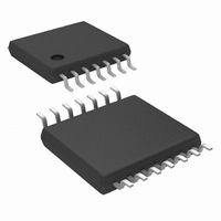
LM2852YMXA-2.5/NOPB National Semiconductor, LM2852YMXA-2.5/NOPB Datasheet - Page 9

LM2852YMXA-2.5/NOPB
Manufacturer Part Number
LM2852YMXA-2.5/NOPB
Description
IC REG SYNC BUCK 2A 2.5V 14TSSOP
Manufacturer
National Semiconductor
Series
PowerWise®, SIMPLE SWITCHER®r
Type
Step-Down (Buck)r
Datasheet
1.LM2852YMXA-3.3NOPB.pdf
(14 pages)
Specifications of LM2852YMXA-2.5/NOPB
Internal Switch(s)
Yes
Synchronous Rectifier
Yes
Number Of Outputs
1
Voltage - Output
2.5V
Current - Output
2A
Frequency - Switching
500kHz
Voltage - Input
2.85 ~ 5.5 V
Operating Temperature
-40°C ~ 125°C
Mounting Type
Surface Mount
Package / Case
14-TSSOP Exposed Pad, 14-eTSSOP 14-HTSSOP
For Use With
LM2852Y-2.5EVAL - BOARD EVAL LM2852Y-2.5
Lead Free Status / RoHS Status
Lead free / RoHS Compliant
Power - Output
-
Other names
*LM2852YMXA-2.5
*LM2852YMXA-2.5/NOPB
LM2852YMXA-2.5
*LM2852YMXA-2.5/NOPB
LM2852YMXA-2.5
Available stocks
Company
Part Number
Manufacturer
Quantity
Price
Company:
Part Number:
LM2852YMXA-2.5/NOPB
Manufacturer:
NS/TI
Quantity:
17
Block Diagram
Applications Information
The LM2852 is a DC-DC synchronous buck regulator be-
longing to National Semiconductor’s SIMPLE SWITCHER
family. Integration of the PWM controller, power switches
and compensation network greatly reduces the component
count required to implement a switching power supply. A
typical application requires only four components: an input
capacitor, a soft-start capacitor, an output filter capacitor and
an output filter inductor.
INPUT CAPACITOR (C
Fast switching of large currents in the buck converter places
a heavy demand on the voltage source supplying PVIN. The
input capacitor, C
needs to draw a burst of current from the supply. The RMS
current rating and the voltage rating of the C
therefore important in the selection of C
specification can be approximated by:
where D is the duty cycle, V
filtering of the supply. Trace resistance and inductance de-
grade the benefits of the input capacitor, so C
placed very close to PVIN in the layout. A 22 µF or 47 µF
ceramic capacitor is typically sufficient for C
with the large input capacitance a smaller capacitor may be
added such as a 1µF ceramic for higher frequency filtering.
SOFT-START CAPACITOR (C
The DAC that sets the reference voltage of the error amp
sources a current through a resistor to set the reference
voltage. The reference voltage is one half of the output
voltage of the switcher due to the 200kΩ divider connected
to the SNS pin. Upon start-up, the output voltage of the
switcher tracks the reference voltage with a two to one ratio
as the DAC current charges the capacitance connected to
the reference voltage node. Internal capacitance of 20pF is
permanently attached to the reference voltage node which is
IN
, supplies extra charge when the switcher
IN
)
SS
OUT
)
/V
IN
. C
IN
. The RMS current
IN
IN
also provides
IN
capacitor are
IN
. In parallel
should be
®
9
also connected to the soft-start pin, SS. Adding a soft-start
capacitor externally increases the time it takes for the output
voltage to reach its final level.
The charging time required for the reference voltage can be
estimated using the RC time constant of the DAC resistor
and the capacitance connected to the SS pin. Three RC time
constant periods are needed for the reference voltage to
reach 95% of its final value. The actual start-up time will vary
with differences in the DAC resistance and higher-order
effects.
If little or no soft-start capacitance is connected, then the
start-up time may be determined by the time required for the
current limit current to charge the output filter capacitance.
The capacitor charging equation I = C ∆V/∆t can be used to
estimate the start-up time in this case. For example, a part
with a 3V output, a 100 µF output capacitance and a 3A
current limit threshold would require a time of 100 µs:
Since it is undesirable for the power supply to start up in
current limit, a soft-start capacitor must be chosen to force
the LM2852 to start up in a more controlled fashion based on
the charging of the soft-start capacitance. In this example,
suppose a 3 ms start time is desired. Three time constants
are required for charging the soft-start capacitor to 95% of
the final reference voltage. So in this case RC=1ms. The
DAC resistor, R, is 400 kΩ so C can be calculated to be
2.5nF. A 2.7nF ceramic capacitor can be chosen to yield
approximately a 3ms start-up time.
SOFT-START CAPACITOR (C
CONDITIONS
Various fault conditions such as short circuit and UVLO of
the LM2852 activate internal circuitry designed to control the
voltage on the soft-start capacitor. For example, during a
short circuit current limit event, the output voltage typically
SS
) AND FAULT
20127012
www.national.com


