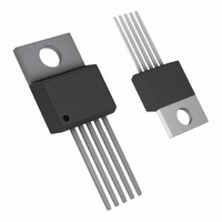
LM2577T-ADJ/NOPB National Semiconductor, LM2577T-ADJ/NOPB Datasheet - Page 23

LM2577T-ADJ/NOPB
Manufacturer Part Number
LM2577T-ADJ/NOPB
Description
IC REG SIMPLE SWITCHER TO-220-5
Manufacturer
National Semiconductor
Series
SIMPLE SWITCHER®r
Type
Step-Up (Boost), Flyback, Forward Converterr
Specifications of LM2577T-ADJ/NOPB
Internal Switch(s)
Yes
Synchronous Rectifier
No
Number Of Outputs
1
Voltage - Output
11.4 ~ 12.6 V
Current - Output
3A
Frequency - Switching
52kHz
Voltage - Input
3.5 ~ 40 V
Operating Temperature
-40°C ~ 125°C
Mounting Type
Through Hole
Package / Case
TO-220-5 (Straight Leads)
Current, Input Bias
100 nA
Current, Output
3 A
Current, Supply
25 mA
Frequency, Oscillator
52 kHz
Package Type
TO-220
Regulation, Line
20 mV
Regulation, Load
20 mV
Regulator Type
Boost (Step-Up)
Resistance, Thermal, Junction To Case
2 °C/W
Temperature, Operating, Range
-40 to +125 °C
Transconductance
3700
Voltage, Gain
800 V/V
Voltage, Input
3.5 to 40 V
Dc To Dc Converter Type
Step Up
Pin Count
5 +Tab
Input Voltage
40V
Output Voltage
11.6 to 12.4V
Switching Freq
48 TO 56KHz
Output Current
3A
Efficiency
80%
Output Type
Adjustable
Switching Regulator
Yes
Load Regulation
50mV
Line Regulation
50mV
Mounting
Through Hole
Input Voltage (min)
3.5V
Operating Temperature Classification
Automotive
For Use With
551011367-061 - BOARD WEBENCH LM2577,LM2585/87
Lead Free Status / RoHS Status
Lead free / RoHS Compliant
Power - Output
-
Lead Free Status / Rohs Status
RoHS Compliant part
Electrostatic Device
Other names
*LM2577T-ADJ
*LM2577T-ADJ/NOPB
LM2577T-ADJ
*LM2577T-ADJ/NOPB
LM2577T-ADJ
Available stocks
Company
Part Number
Manufacturer
Quantity
Price
Company:
Part Number:
LM2577T-ADJ/NOPB
Manufacturer:
TOSHIBA
Quantity:
7 600
Application Hints
C. Calculate the minimum value of C
D. Calculate the maximum ESR of the +V
output capacitors in parallel.
This formula can also be used to calculate the maximum
ESR of a single output regulator.
At this point, refer to this same section in the Step-Up
Regulator Design Procedurefor more information regard-
ing the selection of C
3. Output Voltage Selection
This section is for applications using the LM1577-ADJ/
LM2577-ADJ. Skip this section if the LM1577-12/LM2577-12
or LM1577-15/LM2577-15 is being used.
With the LM1577-ADJ/LM2577-ADJ, the output voltage is
given by
Duty Cycle
Primary Current Variation
Peak Primary Current
Switch Voltage when Off
Diode Reverse Voltage
Average Diode Current
Peak Diode Current
Short Circuit Diode Current
Power Dissipation of
LM1577/LM2577
OUT
.
(Continued)
C
FIGURE 19. Flyback Regulator Formulas
OUT
and −V
V
I
SW(OFF)
I
I
D(AVE)
D(PK)
P(PK)
∆I
V
P
D
OUT
R
D
P
23
Resistors R1 and R2 divide the output voltage down so it can
be compared with the LM1577-ADJ/LM2577-ADJ internal
1.23V reference. For a desired output voltage V
R1 and R2 so that
4. Diode Selection
The switching diode in a flyback converter must withstand
the reverse voltage specified by the following equation.
A suitable diode must have a reverse voltage rating greater
than this. In addition it must be rated for more than the
average and peak diode currents listed in Figure 19.
5. Input Capacitor Selection
The primary of a flyback transformer draws discontinuous
pulses of current from the input supply. As a result, a flyback
regulator generates more noise at the input supply than a
V
OUT
01146878
V
+
OUT
N (V
I
LOAD
= 1.23V (1 + R1/R2)
IN
−
V
SAT
)
www.national.com
OUT
, select


