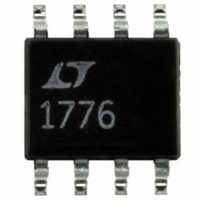
LT1776CS8 Linear Technology, LT1776CS8 Datasheet - Page 15

LT1776CS8
Manufacturer Part Number
LT1776CS8
Description
IC SW REG STEP-DOWN HI-EFF 8SOIC
Manufacturer
Linear Technology
Type
Step-Down (Buck)r
Datasheet
1.LT1776CS8PBF.pdf
(20 pages)
Specifications of LT1776CS8
Internal Switch(s)
Yes
Synchronous Rectifier
No
Number Of Outputs
1
Voltage - Output
1.24 ~ 34 V
Current - Output
700mA
Frequency - Switching
200kHz
Voltage - Input
7.4 ~ 40 V
Operating Temperature
0°C ~ 125°C
Mounting Type
Surface Mount
Package / Case
8-SOIC (3.9mm Width)
Lead Free Status / RoHS Status
Contains lead / RoHS non-compliant
Power - Output
-
Available stocks
Company
Part Number
Manufacturer
Quantity
Price
Part Number:
LT1776CS8
Manufacturer:
LINEAR/凌特
Quantity:
20 000
Part Number:
LT1776CS8#PBF
Manufacturer:
LT/凌特
Quantity:
20 000
Part Number:
LT1776CS8#TRPBF
Manufacturer:
LINEAR/凌特
Quantity:
20 000
chosen to be significantly above the SHDN pin input
current to minimize its error contribution, but signifi-
cantly below the typical 3.8mA the LT1776 draws in
lockout mode. Resistor R4 is then chosen to yield this
same 200 A, less 2.5 A, with the desired V
voltage minus 1.25V applied across it. (The 2.5 A factor
is an allowance to minimize error due to SHDN pin input
current.)
Behavior is as follows: Normal operation is observed at the
nominal input voltage of 40V. As the input voltage is
decreased to roughly 32V, switching action will stop, V
will drop to zero, and the LT1776 will draw its V
quiescent currents from the V
input voltage, typically 14V or so at 25 C, the voltage on
the SHDN pin will drop to the shutdown threshold, and the
part will draw its shutdown current only from the V
The resistive divider of R4 and R5 will continue to draw
power from V
SHDN pin lockout threshold is relatively accurate includ-
ing temperature effects, the SHDN pin shutdown thresh-
old is more coarse, and exhibits considerably more
temperature drift. Nevertheless the shutdown threshold
will always be well below the lockout threshold.)
TYPICAL APPLICATIONS
IN
. (The user should be aware that while the
V
IN
IN
supply. At a much lower
R4
158k
1%
R5
6.19k
1%
U
Figure 5. User Programmable Undervoltage Lockout
+
C5
C1
IN
1
6
IN
and V
SHDN
SYNC
IN
UVLO
LT1776
GND
V
rail.
OUT
IN
CC
5
4
V
V
SW
V
CC
FB
C
2
3
7
8
Minimum Size Inductor Application
Figure 4a employs power path parts that are capable of
delivering the full rated output capability of the LT1776.
Potential users with low output current requirements may
be interested in substituting a physically smaller and less
costly power inductor. The circuit shown in Figure 6a is
topologically identical to the basic application, but speci-
fies a much smaller inductor. This circuit is capable of
delivering up to 400mA at 5V, or, up to 500mA at 3.3V. The
only disadvantage is that due to the increased resistance
in the inductor, the circuit is no longer capable of with-
standing indefinite short circuits to ground. The LT1776
will still current limit at its nominal I
overheat the inductor. Momentary short circuits of a few
seconds or less can still be tolerated. Typical efficiency is
shown in Figure 6b.
R3
C3
D1
C4
L1
+
C2
R1
R2
1776 F05
V
OUT
LIM
value, but this will
LT1776
15


