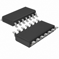
LTC1148LCS Linear Technology, LTC1148LCS Datasheet

LTC1148LCS
Specifications of LTC1148LCS
Available stocks
Related parts for LTC1148LCS
LTC1148LCS Summary of contents
Page 1
... For operation up to 48V input, see the LTC1149 and LTC1159 data sheets and Application Note 54. , LTC and LT are registered trademarks of Linear Technology Corporation. Burst Mode is a trademark of Linear Technology Corporation. * LTC1148L and LTC1148L-3.3 only. Protected by U.S. Patents, including 6580258, 5481178. ...
Page 2
... LTC1148HVCN-3.3 11 SGND LTC1148CN-5 10 SHUTDOWN LTC1148HVCN LTC1148CS + 8 SENSE LTC1148HVCS S PACKAGE LTC1148LCS 14-LEAD PLASTIC SO LTC1148CS-3.3 LTC1148HVCS-3.3 = 70°C/ W (N) JA LTC1148LCS-3.3 = 110°C/ W (S) JA LTC1148CS-5 LTC1148HVCS-5 LTC1148HVIS unless otherwise noted. MIN TYP MAX ● 1.21 1.25 1.29 ● 0.2 1 ● 3.23 3.33 3.43 ● 4.90 5 ...
Page 3
ELECTRICAL C HARA TERISTICS C temperature range, otherwise specifications are at T SYMBOL PARAMETER V – V Current Sense Threshold Voltage 8 7 LTC1148, LTC1148HV, LTC1148L LTC1148-3.3, LTC1148HV-3.3 LTC1148L-3.3 LTC1148-5, LTC1148HV-5 V Shutdown Pin Threshold 10 I Shutdown Pin Input ...
Page 4
LTC1148 LTC1148-3.3/LTC1148-5 ELECTRICAL C HARA TERISTICS C Note 1: Absolute Maximum Ratings are those values beyond which the life of a device may be impaired. Note calculated from the ambient temperature T J dissipation P according to ...
Page 5
W U TYPICAL PERFOR A Gate Charge Supply Current 100nC 50nC 140 200 260 OPERATING FREQUENCY (kHz) LTC1148 ...
Page 6
LTC1148 LTC1148-3.3/LTC1148 CTIO AL DIAGRA SGND 11 SLEEP + S – – TH2 TH1 + TEST CIRCUIT + V IN 390pF 10nF 3300pF Pin 9 connection shown for LTC1148-3.3 ...
Page 7
U OPERATIO The LTC1148 series uses a current mode, constant off- time architecture to synchronously switch an external pair of complementary power MOSFETs. Operating fre- quency is set by an external capacitor at the timing capacitor Pin 4. The output ...
Page 8
LTC1148 LTC1148-3.3/LTC1148 APPLICATIO S I FOR ATIO The basic LTC1148 series application circuit (fixed output versions) is shown in Figure 1. External compo- nent selection is driven by the load requirement, and begins with the selection of R ...
Page 9
U U APPLICATIO S I FOR ATIO 1000 SENSE – V 800 600 400 V = 12V 200 0 0 200 100 FREQUENCY (kHz) Figure 3. Timing Capacitor Value ) ) V 1 OUT f ...
Page 10
LTC1148 LTC1148-3.3/LTC1148 APPLICATIO S I FOR ATIO level threshold MOSFETs (V GS(TH) recommended. The LTC1148/LTC1148HV series supply voltage must always be less than the absolute maximum V ratings for the MOSFETs. GS The maximum output current I determines ...
Page 11
U U APPLICATIO S I FOR ATIO In surface mount applications multiple capacitors may have to be paralleled to meet the capacitance, ESR, or RMS current handling requirements of the application. Aluminum electrolytic and dry tantalum capacitors are both available ...
Page 12
LTC1148 LTC1148-3.3/LTC1148 APPLICATIO S I FOR ATIO LTC1148 DC supply current is 160µA for no load, and increases proportionally with load constant 1.6mA after the LTC1148 series has entered continu- ous mode. Because the DC ...
Page 13
U U APPLICATIO S I FOR ATIO and δ = δ = 0.007(63 – 25) = 0.27. The required for each MOSFET can now be calculated: 12(0.25) P- 0.12Ω DS(ON) 2 5(2) (1.27) 12(0.25) ...
Page 14
LTC1148 LTC1148-3.3/LTC1148 APPLICATIO S I FOR ATIO With the addition of R3, a current is generated through R1 causing an offset of OFFSET OUT > 25mV, the ...
Page 15
U U APPLICATIO S I FOR ATIO Board Layout Checklist When laying out the printed circuit board, the following checklist should be used to ensure proper operation of the LTC1148 series. These items are also illustrated graphi- cally in the ...
Page 16
LTC1148 LTC1148-3.3/LTC1148-5 TYPICAL APPLICATIO S 1/2 Si4532 1 14 P-DRIVE N-DRIVE 1µ 100µH LTC1148HV PGND SGND 390pF INTV SHUTDOWN SHUTDOWN ...
Page 17
TYPICAL APPLICATIO S MMSF3P02HD 1 14 P-DRIVE N-DRIVE 1µ LTC1148L-3 PGND SGND 270pF INTV SHUTDOWN SHUTDOWN ...
Page 18
LTC1148 LTC1148-3.3/LTC1148-5 TYPICAL APPLICATIO S 1µ 390pF 1N4148 V OUT C C 3300pF Figure 16 14V Input Voltage to 5V/1A Regulator with Current Foldback + C T 10nF 390pF R 1k Figure ...
Page 19
... MOLD FLASH OR PROTRUSIONS SHALL NOT EXCEED .006" (0.15mm) Information furnished by Linear Technology Corporation is believed to be accurate and reliable. However, no responsibility is assumed for its use. Linear Technology Corporation makes no represen- tation that the interconnection of its circuits as described herein will not infringe on existing patent rights. ...
Page 20
... Nonsynchronous Equivalent to LTC1148, 8-Pin V < 48V, Standard Threshold MOSFETs IN V < 40V, Logic Level MOSFETs IN Nonsynchronous 8-Pin Internal Switch Nonsynchronous Internal Switch Synchronous N-Channel, Constant Frequency Auxiliary Linear Regulator, 5V Standby in Shutdown LT/TP 0604 1K REV D • PRINTED IN USA © LINEAR TECHNOLOGY CORPORATION 1993 114835fd ...


