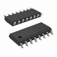
LM3524DMX/NOPB National Semiconductor, LM3524DMX/NOPB Datasheet - Page 18

LM3524DMX/NOPB
Manufacturer Part Number
LM3524DMX/NOPB
Description
IC REG PULSE WIDTH MOD 16-SOIC
Manufacturer
National Semiconductor
Type
Step-Down (Buck), Step-Up (Boost), Flybackr
Datasheet
1.LM2524DNNOPB.pdf
(22 pages)
Specifications of LM3524DMX/NOPB
Internal Switch(s)
Yes
Synchronous Rectifier
No
Number Of Outputs
1
Voltage - Output
5V
Current - Output
200mA
Frequency - Switching
550kHz
Voltage - Input
8 ~ 40 V
Operating Temperature
0°C ~ 125°C
Mounting Type
Surface Mount
Package / Case
16-SOIC (3.9mm Width)
Power - Output
1W
Number Of Pwm Outputs
2
On/off Pin
Yes
Adjustable Output
Yes
Switching Freq
350KHz
Duty Cycle
49%
Operating Supply Voltage (max)
40V
Output Current
200A
Output Voltage
60V
Synchronous Pin
Yes
Rise Time
200ns
Fall Time
100ns
Operating Temperature Classification
Commercial
Mounting
Surface Mount
Pin Count
16
Package Type
SOIC N
Lead Free Status / RoHS Status
Lead free / RoHS Compliant
Other names
*LM3524DMX
*LM3524DMX/NOPB
LM3524DMX
*LM3524DMX/NOPB
LM3524DMX
www.national.com
In calculating the output capacitor C
supplies I
time will be some ΔV
lator. Calculation of C
where: C
ΔV
Calculation of inductor L1 is as follows:
V
IN
is applied across L1
o
is the p-p output ripple
o
o
is in farads, f is the switching frequency,
during t
ON
c
. The voltage change on C
o
= ΔV
is:
o
or the output ripple of the regu-
o
it can be seen that C
o
during this
o
18
where: L1 is in henrys, f is the switching frequency in Hz
To apply the above theory, a complete step-up switching reg-
ulator is shown in Figure 20. Since V
V
amplifier's inverting input. The output voltage is:
The network D1, C1 forms a slow start circuit.
This holds the output of the error amplifier initially low thus
reducing the duty-cycle to a minimum. Without the slow start
circuit the inductor may saturate at turn-on because it has to
supply high peak currents to charge the output capacitor from
0V. It should also be noted that this circuit has no supply re-
jection. By adding a reference voltage at the non-inverting
input to the error amplifier, see Figure 21, the input voltage
variations are rejected.
The LM3524D can also be used in inductorless switching
regulators. Figure 22 shows a polarity inverter which if con-
nected to Figure 20 provides a −15V unregulated output.
IN
. The input voltage is divided by 2 to bias the error
IN
is 5V, V
REF
is tied to


