LM2576T-ADJG ON Semiconductor, LM2576T-ADJG Datasheet - Page 8
LM2576T-ADJG
Manufacturer Part Number
LM2576T-ADJG
Description
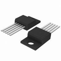
IC REG SW 3A ADJ STEPDWN TO220-5
Manufacturer
ON Semiconductor
Type
Step-Down (Buck)r
Datasheet
1.LM2576D2T-ADJR4G.pdf
(28 pages)
Specifications of LM2576T-ADJG
Internal Switch(s)
Yes
Synchronous Rectifier
No
Number Of Outputs
1
Voltage - Output
1.23 ~ 37 V
Current - Output
3A
Frequency - Switching
52kHz
Voltage - Input
7 ~ 40 V
Operating Temperature
-40°C ~ 125°C
Mounting Type
Through Hole
Package / Case
TO-220-5 (Straight Leads)
Output Voltage
1.23 V to 37 V
Output Current
3 A
Input Voltage
4.75 V to 40 V
Switching Frequency
52 KHz
Operating Temperature Range
- 40 C to + 125 C
Mounting Style
Through Hole
Duty Cycle (max)
98 %
Primary Input Voltage
40V
No. Of Outputs
1
No. Of Pins
5
Filter Terminals
Through Hole
Rohs Compliant
Yes
Dc
0739
Lead Free Status / RoHS Status
Lead free / RoHS Compliant
Power - Output
-
Lead Free Status / Rohs Status
Lead free / RoHS Compliant
Other names
LM2576T-ADJGOS
Available stocks
Company
Part Number
Manufacturer
Quantity
Price
Company:

Part Number:
LM2576T-ADJG
Manufacturer:
ON
Quantity:
250
Company:
Part Number:
LM2576T-ADJG
Manufacturer:
ONSEMICONDUCTOR
Quantity:
1 324
Part Number:
LM2576T-ADJG
Manufacturer:
ON/安森美
Quantity:
20 000


circuit board is very important. Rapidly switching currents
associated with wiring inductance, stray capacitance and
parasitic inductance of the printed circuit board traces can
generate
electromagnetic interferences (EMI) and affect the desired
operation. As indicated in the Figure 15, to minimize
inductance and ground loops, the length of the leads
indicated by heavy lines should be kept as short as possible.
ground plane construction should be used.
As in any switching regulator, the layout of the printed
For best results, single−point grounding (as indicated) or
voltage
7.0 V − 40 V
Unregulated
DC Input
7.0 V − 40 V
Unregulated
transients
DC Input
C
100 mF
in
which
V
C
100 mF
in
1
in
3
V
in
1
Adjustable
C
C
D1
L1
R1
R2
can
Adjustable Output Voltage Versions
GN
D
LM2576
in
out
PCB LAYOUT GUIDELINES
3
Fixed Output Voltage Versions
Figure 15. Typical Test Circuit
Fixed Output
−
−
−
−
−
−
GN
D
LM2576
generate
100 mF, 75 V, Aluminium Electrolytic
1000 mF, 25 V, Aluminium Electrolytic
Schottky, MBR360
100 mH, Pulse Eng. PE−92108
2.0 k, 0.1%
6.12 k, 0.1%
5
http://onsemi.com
V out + V
R2 + R1
Where V
between 1.0 k and 5.0 k
ON/OFF
5
LM2576
2
4
Output
Feedback
ref
ON/OFF
ref
8
= 1.23 V, R1
V out
V ref
2
4
Feedback
Output
1.0 ) R2
(emitter of the internal switch) of the LM2576 should be
kept to a minimum in order to minimize coupling to sensitive
circuitry.
important to keep the sensitive feedback wiring short. To
assure this, physically locate the programming resistors near
to the regulator, when using the adjustable version of the
LM2576 regulator.
– 1.0
On the other hand, the PCB area connected to the Pin 2
Another sensitive part of the circuit is the feedback. It is
100 mH
D1
MBR360
R1
L1
100 mH
D1
MBR360
L1
C
1000 mF
out
C
1000 mF
out
R2
R1
Load
V
out
5,000 V
Load
V
out
Related parts for LM2576T-ADJG
Image
Part Number
Description
Manufacturer
Datasheet
Request
R

Part Number:
Description:
Manufacturer:
ON Semiconductor
Datasheet:

Part Number:
Description:
IC REG SW 3A 5V STEPDOWN TO220-5
Manufacturer:
ON Semiconductor
Datasheet:

Part Number:
Description:
IC REG SW 3A 5V STEPDOWN TO220-5
Manufacturer:
ON Semiconductor
Datasheet:
Part Number:
Description:
IC REG SW 3A 3.3V STPDWN TO220-5
Manufacturer:
ON Semiconductor
Datasheet:
Part Number:
Description:
IC REG SW 3A ADJ STEPDWN TO220-5
Manufacturer:
ON Semiconductor
Datasheet:
Part Number:
Description:
IC REG SW 3A 3.3V STPDWN TO220-5
Manufacturer:
ON Semiconductor
Datasheet:
Part Number:
Description:
IC REG SW 3A 12V STEPDWN TO220-5
Manufacturer:
ON Semiconductor
Datasheet:
Part Number:
Description:
IC REG SW 3A 15V STEPDWN TO220-5
Manufacturer:
ON Semiconductor
Datasheet:
Part Number:
Description:
IC REG SW 3A 12V STEPDWN TO220-5
Manufacturer:
ON Semiconductor
Datasheet:
Part Number:
Description:
IC REG SW 3A 15V STEPDWN TO220-5
Manufacturer:
ON Semiconductor
Datasheet:
Part Number:
Description:
Switching Converters, Regulators & Controllers 15V 3A Buck PWM
Manufacturer:
ON Semiconductor
Part Number:
Description:
ON Semiconductor [VOLTAGE REGULATOR]
Manufacturer:
ON Semiconductor
Datasheet:
Part Number:
Description:
357-036-542-201 CARDEDGE 36POS DL .156 BLK LOPRO
Manufacturer:
ON Semiconductor
Datasheet:
Part Number:
Description:
357-036-542-201 CARDEDGE 36POS DL .156 BLK LOPRO
Manufacturer:
ON Semiconductor
Datasheet:
Part Number:
Description:
357-036-542-201 CARDEDGE 36POS DL .156 BLK LOPRO
Manufacturer:
ON Semiconductor
Datasheet: