MAX4845ELT+T Maxim Integrated Products, MAX4845ELT+T Datasheet - Page 6
MAX4845ELT+T
Manufacturer Part Number
MAX4845ELT+T
Description
IC CTLR OVP 5.8V 6-UDFN
Manufacturer
Maxim Integrated Products
Type
Overvoltage Protection Controllerr
Datasheet
1.MAX4845ELTT.pdf
(10 pages)
Specifications of MAX4845ELT+T
Applications
Cell Phones, Digital Cameras, Media Players
Mounting Type
Surface Mount
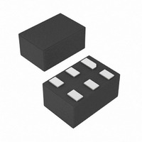
Package / Case
6-µDFN
Lead Free Status / RoHS Status
Lead free / RoHS Compliant
Other names
MAX4845ELT+T
MAX4845ELT+TTR
MAX4845ELT+TTR


Overvoltage Protection Controllers with
Low Standby Current
The MAX4843–MAX4846 provide up to 28V overvoltage
protection for low-voltage systems. When the input volt-
age exceeds the overvoltage trip level, the
MAX4843–MAX4846 turn off a low-cost external n-chan-
nel FET(s) to prevent damage to the protected compo-
nents. An internal charge pump (see the Functional
Diagram ) drives the FET gate for a simple, robust solu-
tion. On power-up, the device waits for 50ms before dri-
ving GATE high. The open-drain FLAG output is kept at
high impedance for an additional 50ms after GATE goes
high before deasserting. The FLAG output asserts high
immediately to an overvoltage fault.
The MAX4843/MAX4844/MAX4845 have a fixed 4.15V
typical UVLO level, the MAX4845C/MAX4845D have a
2.2V typical UVLO, and the MAX4846 has a 2.5V typi-
cal UVLO. When V
driver is held low and FLAG is asserted.
The MAX4843 has a 7.4V typical OVLO; the MAX4844
has a 6.35V typical OVLO; and the MAX4845 has a
5.8V typical OVLO. The MAX4846 has a 4.65V typical
overvoltage threshold. When V
the GATE driver is held low and FLAG is asserted.
The open-drain FLAG output is used to signal to the
host system that there is a fault with the input voltage.
FLAG asserts immediately to an overvoltage fault.
FLAG is held high for 50ms after GATE turns on before
deasserting. Connect a pullup resistor from FLAG to
the logic I/O voltage of the host system.
An on-chip charge pump is used to drive GATE above
IN, allowing the use of low-cost n-channel MOSFETs. The
charge pump operates from the internal 5.5V regulator.
The actual GATE output voltage tracks approximately
two times V
level is exceeded, whichever comes first. The
MAX4843 has a 7.4V typical OVLO, therefore GATE
remains relatively constant at about 10.5V for 5.5V <
V
this can be as low as 5.5V. The GATE output voltage as
a function of input voltage is shown in the Typical
Operating Characteristics .
6
IN
_______________________________________________________________________________________
< 7.4V. The MAX4845 has a 5.8V typical OVLO, but
IN
until V
Undervoltage Lockout (UVLO)
Overvoltage Lockout (OVLO)
IN
IN
is less than the UVLO, the GATE
Detailed Description
exceeds 5.5V or the OVLO trip
IN
is greater than OVLO,
FLAG Output
GATE Driver
The MAX4843–MAX4846 have an on-board state
machine to control device operation. A flowchart is
shown in Figure 4. On initial power-up, if V
if V
If UVLO < V
a 50ms internal delay. The internal charge pump is
enabled, and GATE begins to be driven above V
the internal charge pump. FLAG is held high during
startup until the FLAG blanking period expires, typically
50ms after the GATE starts going high. At this point the
device is in its on state.
At any time if V
than OVLO, FLAG is driven high and GATE is driven
to ground.
Figure 4. State Diagram
V
IN
IN
< UVLO
> OVLO, GATE is held at 0V, and FLAG is high.
IN
< OVLO, the device enters startup after
IN
drops below UVLO or V
GATE DRIVEN HIGH
TIME STARTS
OVLO CHECK
FLAG = HIGH
FLAG = HIGH
FLAG = HIGH
FLAG = LOW
COUNTING
GATE HIGH
STANDBY
STARTUP
GATE = 0
GATE = 0
ON
V
t = 50ms
V
t = 50ms
IN
IN
> UVLO
< OVLO
Device Operation
IN
IN
< UVLO or
is greater
V
IN
> OVLO
IN
by
Related parts for MAX4845ELT+T
Image
Part Number
Description
Manufacturer
Datasheet
Request
R

Part Number:
Description:
MAX7528KCWPMaxim Integrated Products [CMOS Dual 8-Bit Buffered Multiplying DACs]
Manufacturer:
Maxim Integrated Products
Datasheet:
Part Number:
Description:
Single +5V, fully integrated, 1.25Gbps laser diode driver.
Manufacturer:
Maxim Integrated Products
Datasheet:
Part Number:
Description:
Single +5V, fully integrated, 155Mbps laser diode driver.
Manufacturer:
Maxim Integrated Products
Datasheet:
Part Number:
Description:
VRD11/VRD10, K8 Rev F 2/3/4-Phase PWM Controllers with Integrated Dual MOSFET Drivers
Manufacturer:
Maxim Integrated Products
Datasheet:
Part Number:
Description:
Highly Integrated Level 2 SMBus Battery Chargers
Manufacturer:
Maxim Integrated Products
Datasheet:
Part Number:
Description:
Current Monitor and Accumulator with Integrated Sense Resistor; ; Temperature Range: -40°C to +85°C
Manufacturer:
Maxim Integrated Products
Part Number:
Description:
TSSOP 14/A�/RS-485 Transceivers with Integrated 100O/120O Termination Resis
Manufacturer:
Maxim Integrated Products
Part Number:
Description:
TSSOP 14/A�/RS-485 Transceivers with Integrated 100O/120O Termination Resis
Manufacturer:
Maxim Integrated Products
Part Number:
Description:
QFN 16/A�/AC-DC and DC-DC Peak-Current-Mode Converters with Integrated Step
Manufacturer:
Maxim Integrated Products
Part Number:
Description:
TDFN/A/65V, 1A, 600KHZ, SYNCHRONOUS STEP-DOWN REGULATOR WITH INTEGRATED SWI
Manufacturer:
Maxim Integrated Products
Part Number:
Description:
Integrated Temperature Controller f
Manufacturer:
Maxim Integrated Products
Part Number:
Description:
SOT23-6/I�/45MHz to 650MHz, Integrated IF VCOs with Differential Output
Manufacturer:
Maxim Integrated Products
Part Number:
Description:
SOT23-6/I�/45MHz to 650MHz, Integrated IF VCOs with Differential Output
Manufacturer:
Maxim Integrated Products
Part Number:
Description:
EVALUATION KIT/2.4GHZ TO 2.5GHZ 802.11G/B RF TRANSCEIVER WITH INTEGRATED PA
Manufacturer:
Maxim Integrated Products
Part Number:
Description:
QFN/E/DUAL PCIE/SATA HIGH SPEED SWITCH WITH INTEGRATED BIAS RESISTOR
Manufacturer:
Maxim Integrated Products
Datasheet: