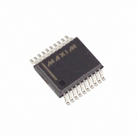
MAX4507CAP+ Maxim Integrated Products, MAX4507CAP+ Datasheet - Page 7

MAX4507CAP+
Manufacturer Part Number
MAX4507CAP+
Description
IC SIGNAL LINE PROTECTOR 20-SSOP
Manufacturer
Maxim Integrated Products
Type
Overvoltage protectionr
Datasheet
1.MAX4507CWN.pdf
(12 pages)
Specifications of MAX4507CAP+
Applications
Control systems
Mounting Type
Surface Mount
Package / Case
20-SSOP
Lead Free Status / RoHS Status
Lead free / RoHS Compliant
The MAX4506/MAX4507 protect other ICs from over-
voltage by clamping its output voltage to the supply
rails. If the power supplies to the device are off, the
device clamps the output to 0V. The MAX4506/
MAX4507 provide protection for input signals up to
±36V with the power supplies on and ±40V with the
power supplies off.
The MAX4506/MAX4507 protect other integrated cir-
cuits connected to its output from latching up. Latchup
is caused by parasitic SCR(s) within the IC turning on,
and can occur when the supply voltage applied to the
IC exceeds the specified operating range. Latchup can
also occur when signal voltage is applied before the
power-supply voltage. When in a latchup state, the cir-
cuit draws excessive current and may continue to draw
excessive current even after the overvoltage condition
is removed. A continuous latchup condition may dam-
age the device permanently. Such “faults” are com-
monly encountered in modular control systems where
power supplies to interconnected modules may be
interrupted and reestablished at random. Faults can
happen during production testing, maintenance, start-
up, or a power failure.
Figure 1 shows the normal complementary pair (N1 and
P1) found in many common analog switches. In addi-
tion to these transistors, the MAX4506/MAX4507 also
contain comparators and sensing and clamping circuitry
to control the state of N1 and P1. During normal opera-
* Connect all unused inputs to a hard voltage within the supply range (e.g., V+, V-, or GND).
MAX4506
DIP/SO
1, 2, 3
5, 6, 7
8-Pin
—
—
—
4
8
15, 16, 17
DIP/SO
18-Pin
1, 2, 3
10–14
PIN
4–8
18
_______________________________________________________________________________________
—
9
MAX4507
Detailed Description
16, 17, 19
20-Pin
SSOP
1, 2, 4
11–15
3, 18
5–9
10
20
OUT8, OUT7, OUT6, OUT5, OUT4
Fault-Protected, High-Voltage
IN4, IN5, IN6, IN7, IN8
OUT3, OUT2, OUT1
IN1, IN2, IN3
NAME*
N.C.
V+
V-
tion, N1 and P1 remain on with a typical 65Ω on-resis-
tance between IN and OUT.
The on-board comparators and sensing circuitry moni-
tor the input voltage for possible overvoltage faults.
Figure 1. Simplified Internal Structure
Signal-Line Protectors
IN
+15V
-15V
-15V
+15V
SWITCH
SWITCH
SENSE
SENSE
Signal Inputs 1, 2, 3
Signal Inputs 4, 5, 6, 7, 8
Negative Supply Voltage Input
Signal Outputs 8, 7, 6, 5, 4
Signal Outputs 3, 2, 1
Positive Supply-Voltage Input
No Connection. Not internally connected.
N3
COMPARATOR
P3
COMPARATOR
N-CHANNEL
P-CHANNEL
DRIVER
DRIVER
N1
FUNCTION
Pin Description
P1
+V(+15V)
-V(-15V)
CLAMP
CLAMP
N2
P2
OUT
7


