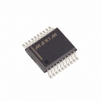
MAX4507CAP+ Maxim Integrated Products, MAX4507CAP+ Datasheet - Page 9

MAX4507CAP+
Manufacturer Part Number
MAX4507CAP+
Description
IC SIGNAL LINE PROTECTOR 20-SSOP
Manufacturer
Maxim Integrated Products
Type
Overvoltage protectionr
Datasheet
1.MAX4507CWN.pdf
(12 pages)
Specifications of MAX4507CAP+
Applications
Control systems
Mounting Type
Surface Mount
Package / Case
20-SSOP
Lead Free Status / RoHS Status
Lead free / RoHS Compliant
Each of the protectors in a MAX4506/MAX4507 may be
used as a switched resistor, independent of the func-
tions of other elements in the same package. For exam-
ple, Figure 4 shows a MAX4506 with two of the
protectors used to protect the input of an op amp, and
the third element used to sequence a power supply.
Combining the circuits of Figures 3 and 4 produces a
delayed action on the switched +15V, as well as
smooth application of signals to the amplifier input.
Figure 5 shows MAX4506 used in front of a MAX338
unprotected 1-to-8 multiplexer. With supplies at ±15V,
V
MAX338 goes to ±14V. With supplies off, V
0V while the inputs remain at ±25V.
Figure 4. Power-Supply Sequencing
Figure 5. Protecting a MAX338 with a MAX4506
OUT
+25V
-25V
-15V
1
2
4
3
of the MAX4506 clamps to ±15V; V
1
2
3
4
IN1
IN2
IN3
V-
MAX4506
MAX4506
Protectors as Circuit Elements
_______________________________________________________________________________________
OV
OUT1
OUT2
OUT3
6
8
7
5
V+
+3V
+15V
R
8
7
6
5
L
+5V
-5V
1
2
3
4
5
6
7
8
A
EN
V-
NO1
NO2
NO3
NO4
V
O
OUT
100kΩ
MAX338
OP AMP
-15V
SWITCHED +15V
GND
NO5
NO6
NO7
NO9
OUT
A1
A2
V+
Fault-Protected, High-Voltage
OUT
P
16
15
14
13
12
11
10
9
goes to
+15V
of the
+15V
Use the MAX4506 with a MAX338 to enhance voltage
handling capability (Figure 6). The MAX4506 and
MAX338 share almost equal voltage drops in this con-
figuration. For example, applying ±40V on pins 1 and 2
of the MAX4506 causes a voltage drop of about 26V
across pin 1 of the MAX4506 to pin 4 of the MAX338,
and a voltage drop of about 28V across pin 4 of the
MAX4506 to pin 8 of the MAX338. Similarly, there is a
26V drop from pin 2 of the MAX4506 to pin 5 of the
MAX338. The system’s performance exceeds each
individual part’s specification because of shared volt-
age drops.
As shown in Figure 7, the MAX4506 can be used in
series with the output of a MAX4508 (1-to-8 multiplexer)
to act as multiplexer or demultiplexer. The MAX4508 is a
fault-protected multiplexer whose inputs are designed to
interface with harsh environments; however, its common
output is not fault protected if connected to outside sig-
nals (i.e., demultiplexer use). If the common output can
see fault signals, then it needs to be protected, and the
MAX4506 can be added to provide complete protection.
Figure 6. SPDT Switch Application
Figure 7. Multiplexer and Demultiplexer Application Using
MAX4506 (or MAX4507) with MAX4508
Signal-Line Protectors
NEW COM
+40V
-40V
-15V
1
2
4
3
1
2
MAX4506
MAX4506
Multiplexer and Demultiplexer
O
7
6
+3V
6
8
7
5
+15V
-15V
+5V
4
5
1
2
3
4
5
6
7
8
MAX338
A
EN
V-
NO1
NO2
NO3
NO4
COM
O
MAX4508
8
GND
NO5
NO6
NO7
NO9
V
A1
A2
V+
OUT
16
15
14
13
12
11
10
9
= -14V
10kΩ
+15V
9


